Installation Instructions
Depending upon the type of equipment you plan to install Ditch Assist on, the exact method will vary somewhat. Ditch Assist is extremely simple to install and move between equipment. The following guidelines should help you determine a suitable installation for your particular equipment.
IMPORTANT: Make sure that Ditch Assist components are installed so that parts, cables and hoses will not be stretched, pinched, or otherwise damaged during the operation of equipment. Keep in mind that cables and hoses may be subject to stretching when the implement is turning, and that components mounted near the hitch or rear of the tractor may come into contact with other parts when cornering.
Proportional Valve Setup
Consult the specific installation instructions that should be included in your installation kit - if these are missing please contact your dealer to obtain them. Ensure you assemble the hydraulic components as shown. Below are common hydraulic assembly instructions for our Bucher and Rexroth valves (other valves may be slightly different):
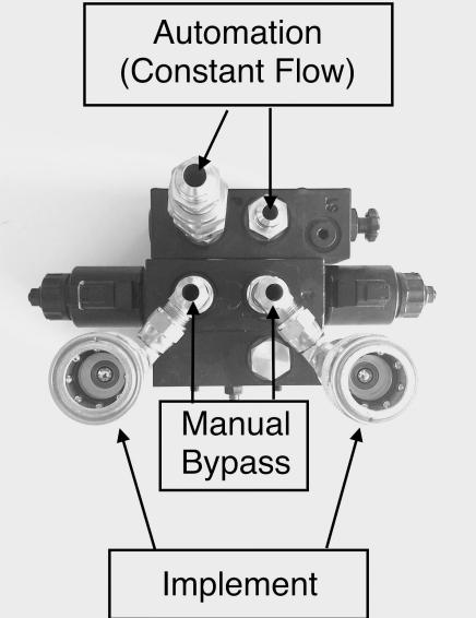
For the Bucher valve, the automation hoses necessary for constant flow should be connected to the external valve block (the block that has the dial). Meanwhile, the fittings for the manual bypass and implement hoses should be attached to the central block, which is situated between the solenoids.
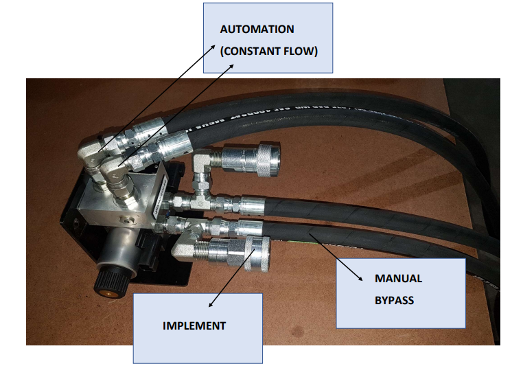
For the Rexroth valve, the hydraulic hoses needed for automation (providing a constant flow) should be connected to the ports located on the valve block's top surface. Meanwhile, the implement connectors and manual bypass fittings should be attached to the ports situated on the valve's side.
Control Module & Valve Installation
Ensure that the Control Module is securely installed either at the implement's front, near the hitch, or at the tractor's rear, with minimal obstructions to the line of sight to the cab. The included magnetic mount can be used for this purpose, or you can fabricate your own if needed. The Control Module can be installed in either a horizontal or vertical orientation.
IMPORTANT: While the Control Module is sealed against weather, and all connectors that plug into it come with waterproof gaskets, we strongly advise installing it with the ports facing downward to prevent water from accumulating in and around them. If the wiring harness connectors are removed from the Control Module, this might allow moisture to infiltrate. Always ensure all port connectors or covers are in place when leaving the Control Module outside.
Position the proportional valve in a place that allows the implement hydraulic hoses to connect to it, and enables the included hoses you attached to the valve to reach the remote ports at the tractor's rear. To prevent damage during operation, the valve must be securely installed. If the provided angle iron mount is used, the pre-drilled holes will align with the valve's mounting holes, and the mounting plate should be either bolted or welded to the equipment.
SUGGESTION: If you intend to use Ditch Assist with multiple different implements, consider permanently mounting the valve on your tractor, as it may be more practical.
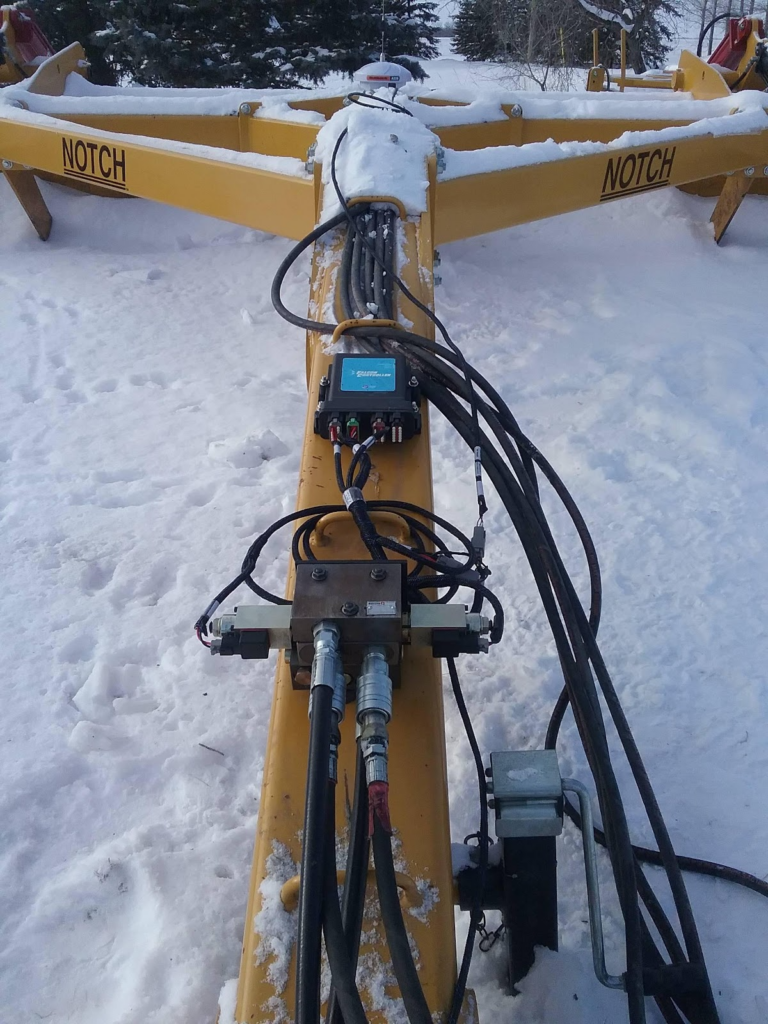
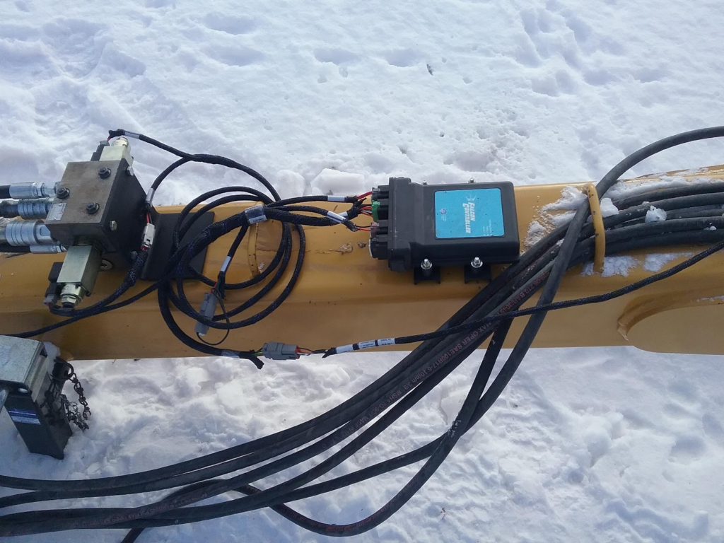
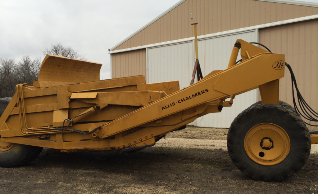
Example Mounting Setup on a Scraper or Land Leveler
Valve bracket should be mounted securely to the implement. Do not weld the bracket with the valve mounted. Remove the module before welding anything to the implement. Make sure the module is mounted where it will not be dislodged by debris, moving parts, or hydraulic lines. Secure all cables and hydraulic lines so they will not be pinched, stretched or damaged during operation.
Connecting the Hydraulic Hoses
The two hoses coming from the P and T ports on the valve, in addition to the hoses for the bypass, need to be connected to the tractor - a total of four hoses. The hydraulic remotes on the tractor that Ditch Assist is connected to should be set to a continuous flow, allowing the valve to raise and lower the implement as required. Depending on the age and size of your tractor, you might need to adjust the flow rate if you observe that the implement is moving up or down too quickly or too slowly. The App also contains settings for valve response - refer to the Settings Menu for more details.
Connecting the Wiring Harness to the Valve
Attach the two plugs from the harness to the connectors on the proportional valve. You might need to swap the connectors later if you notice that the manual up/down controls in the App are functioning in reverse. Specifically, if manually lowering the implement in the App causes it to lift, you'll need to switch the wired connectors on the valve. Refer to the Quick Start guide at the beginning of the manual to understand the process for determining this.
Wiring Harness Installation
The two large Deutsch connectors on the main harness should be plugged into ports A and C of the Ditch Assist Control Module. Each connector has a distinct 'key', ensuring that it's impossible to make incorrect connections. Ports B and D should be left vacant and sealed with the included dust plugs for protection.
Link the power harness directly to the tractor battery terminals and route the cable back to the main harness. Connect it to the power connector on the main harness (it can only fit into one connector, so it's not possible to make an incorrect connection). Make sure to connect the power harness exclusively to the vehicle battery. One of the most frequent troubleshooting issues we encounter is due to the power coming from a trailer plug or an in-cab power strip, which either cannot supply sufficient current to the solenoids or is prone to power surges that cause problems with the microcontrollers.
Finally, connect the GPS breakout cable to the remaining open connector on the harness and route it to the GPS antenna location.
Any slack or excess cables should be secured using ties or other suitable means to prevent them from becoming damaged during machine operation.
GPS Information
Ditch Assist was developed with compatibility in mind, designed to work with a wide range of GPS brands and models. We support both the NMEA 2000 message standard, which is a CAN-based communication protocol, as well as the NMEA 0183, a standard associated with 'serial port' communication.
GPS Requirements and Settings for Ditch Assist
NMEA Output Settings Required
You should configure your GPS to emit the following NMEA messages:
- SET BAUD RATE TO 38,400
- GGA MESSAGE AT 10Hz (5Hz if 10Hz is not available)
- VTG MESSAGE AT 10Hz (5Hz if 10Hz is not available)
- DISABLE ALL OTHER MESSAGES
(If you can't designate a specific message rate for each message, then enable the highest rate for all messages.)
Diagnosing GPS/GNSS Connectivity using the Status LEDs on the Control Module
The Status 2 and Status 1 lights act as indicators when a valid RS232 or CAN based GPS message packet is respectively received. These lights serve as an effective diagnostic tool for GPS connectivity issues. If a GPS device is connected and the light is flashing, this is indicative of successful receipt of a valid GPS message. On the other hand, if the light isn't flashing, this signifies that no GPS messages are being received. Furthermore, the frequency of the flashing lights conveys information about the message rate. For instance, a slow flashing rate, or 1 flash per second, suggests that the GPS device may be outputting messages at only 1Hz. To improve efficiency, it is advisable to adjust the device to output at a rate of 5Hz or 10Hz, which will correspondingly cause the Status LEDs on the Control Module to flash more rapidly.
How to Configure John Deere Smart Antennas
When utilizing a John Deere smart antenna with Ditch Assist, the Ditch Assist GPS cable will provide power to the unit and directly extract the necessary position information into the Control Module. In this setup, there is no need to connect the GPS to the tractor or the GreenStar Display. It is essential to configure the receiver while it is connected to the John Deere CAN system, such as when it is installed on the tractor's roof. Once properly configured, you can remove the receiver and attach it to the implement, connecting it to the Ditch Assist Control Module using the appropriate cable. Ditch Assist will supply power to the receiver and retrieve the required GPS messages from it.
- Press the "Menu" button on your John Deere GreenStar display.
- Scroll to "StarFire Receiver" (or "StarFire 6000" or "StarFire 3000" etc., depending on your model), and select it.
- Once inside the "StarFire Receiver" menu, scroll to "NMEA Strings" and select it.
- You will see a list of NMEA strings such as GGA, VTG, etc. Toggle the strings you need (for Ditch Assist, GGA and VTG) to 'ON'.
- Set the message rate to either 5Hz or 10Hz
- Also, ensure that the BAUD rate is set correctly, typically to 38,400 for Ditch Assist.
- Exit the menu once the changes are complete.
- Your receiver should now be broadcasting the selected NMEA strings. Connect it to the Ditch Assist Control Module and verify that the Status 2 light on the module begins to flash as this indicates that GPS data are being received
How to Configure Trimble/Case IH GNSS Receivers
To enable NMEA messages on Trimble/Case-IH GPS receivers, you can follow these general steps:
1. Access the GPS receiver's settings or configuration menu. This can typically be done through the display unit or the receiver's interface.
2. Look for the section or option related to communication or output settings.
3. Locate the NMEA messages settings or options within the communication settings.
4. Enable or activate the desired NMEA messages. Trimble/Case-IH GPS receivers usually provide options to enable specific NMEA messages, such as GGA, VTG, or others.
5. Adjust the message rate if available. Some receivers allow you to specify the rate at which the NMEA messages are output (e.g., 10Hz or 5Hz).
6. Save the changes and exit the settings menu.
How to Configure Emlid RS2 Receivers
To enable NMEA messages on the Emlid RS2 GNSS receiver, you can follow these steps:
1. Connect to the RS2 GNSS receiver using the ReachView app on your mobile device or web browser.
2. Open the ReachView app and navigate to the "GNSS Settings" or "RTK Settings" section.
3. Look for the option related to NMEA messages or NMEA output. The specific location may vary depending on the version of ReachView, but it is usually found within the GNSS or RTK settings.
4. Enable or toggle the NMEA messages option. You have the option to select specific NMEA message types or configure the message rate.
5. Set the baud rate to 38,400
6. Save the changes or apply the settings.
7. The RS2 GNSS receiver will now output the selected NMEA messages according to the configured settings.
How to Configure Outback GPS Receivers
Many Outback GPS smart antennas are plug-and-play and will provide the required GPS messages over CAN bus automatically when connected to Ditch Assist with our Outback GPS harness. If your Outback antenna has a small circular connector then it likely falls into this category. Otherwise, to manually enable NMEA messages on Outback GPS receivers, you can follow these general steps:
1. Access the GPS receiver's menu or settings. This is typically done through a display or user interface on the device.
2. Look for a section related to communication settings or NMEA output configuration.
3. Within the communication settings, you should find an option to enable NMEA messages or configure the NMEA output.
4. Enable the NMEA output or select the desired NMEA message types you want to receive.
5. Check if there are additional settings to adjust the baud rate and message rate (such as 10Hz or 5Hz).
6. Save the changes and exit the menu or settings.
Please note that specific steps may vary depending on the model and firmware version of your Outback GPS receiver. It is recommended to refer to the user manual or consult the manufacturer's documentation for precise instructions related to your specific model.
GPS Corrections and Accuracy
Ditch Assist relies on a precise GPS signal for optimal performance. If your GPS lacks accuracy, it may impact the performance of Ditch Assist.
IMPORTANT: If you are not using RTK with your own base station, we highly recommend using a subscription-based correction service with a published vertical accuracy of at worst 2-3 inches as a minimum requirement. It is possible that you may find the GPS accuracy provided by your current system to be insufficient. This is not a fault of Ditch Assist, as it simply processes the incoming GPS data it receives.
Ditch Assist is not compatible with low-accuracy correction signals like WAAS or low-accuracy SBAS corrections such as OmniSTAR L1. We recommend, at a minimum, utilizing a subscription-based dual-frequency (L1/L2) satellite-delivered correction signal.
Below are specifications for the recommended GPS corrections:
USE WITH CAUTION:
Subscription-based L1/L2 correction services like CenterPoint RTX, TerraStar, or Atlas. Expect slight fluctuations in elevation readings with these systems (e.g., the machine may experience minor up/down movements even when stationary). Not recommended for use in pancake-flat fields.
SHOULD BE OKAY UNDER MOST CIRCUMSTANCES:
Network RTK Correction through CORS, Cellular, or Long Range Radio link to a remote base station. These corrections typically provide good accuracy for surface grading. Keep in mind that the closer you are to the base station, the better the repeatable accuracy will be. Being near a cell tower does not necessarily mean you are close to the base station. If you don't experience issues with signal dropouts or loss of accuracy, this is a good option.
BEST OPTION FOR RELIABILITY AND ACCURACY:
RTK using your own base station within line-of-sight offers the highest level of accuracy. By setting up your own base station, you can determine the distance and adjust its position if necessary. For optimum accuracy, ensure that you are within 2 miles of the base station. With this type of RTK setup, you should experience minimal fluctuation in elevation readings while stationary, and the implement's hydraulic movements due to RTK fluctuations should be nearly imperceptible.
Please note that while we do not endorse using any correction less accurate than RTK, some users have chosen to use lower accuracy systems and have been satisfied with the performance.
Mounting the GPS Antenna
IMPORTANT: The GPS antenna to be used with Ditch Assist must be mounted on the implement to be controlled and must be attached to a part of the implement that moves up and down in proportion to the cutting edge or blade. Failure to adhere to this principle will result in incorrect operation.
The GPS antenna should also be mounted in a raised position so that it sits above any objects that may cause the satellite signal to be blocked or deflected. Incoming GPS signals that bounce off a metal object near the GPS antenna may contribute to decreased GPS accuracy, so it is important to ensure the GPS antenna is mounted away from any such objects. Also keep in mind that the working position may be considerably lower than the transport position, so a taller mast may be required.
Mounting Your Android Device
The Ditch Assist Kit includes a RAM mount designed for 10” tablets. Use the mount to securely install your device in the tractor cab somewhere you can easily see and tap the screen. You may also wish to power your device to avoid battery drain on your device. (Tablet & charge cables are not included in the standard Ditch Assist kit).