DOWNLOAD PDF VERSION HERE

Operator’s Manual
Modified: Nov 29, 2023
Use Case I: Employing Ditch Assist for Basic Drainage, Grading, and Leveling 7
Use Case II: Utilizing Ditch Assist to Craft & Execute Multi Slope Surface & Subsurface Drains 7
Use Case III: Using Ditch Assist to Design & Execute Multi Slope Planes on Small Fields or Areas 8
CAUTIONS, WARNINGS, STATEMENTS 9
Software End User License Agreement 13
Hardware Warranty Information 14
Getting Started with Ditch Assist 16
Ditch Assist Required Components 16
Ditch Assist Control Module 16
Pulse Width Modulation (PWM) Hydraulic Valve (included in full automation kit) 17
Quick-Start Guide to Using Ditch Assist 20
1. Install Ditch Assist Hardware: 20
2. Connect Tablet to Ditch Assist Control Module 20
3. Verify Implement Hydraulic Control from the Ditch Assist App 21
4. Begin Operating (see appropriate chapters for information) 21
Ditch Assist Operating Principles 22
Understanding How Ditch Assist Works 25
Important GNSS (GPS) Limitations to Understand 25
Control Module & Valve Installation 28
Example Mounting Setup on a Scraper or Land Leveler 29
Connecting the Hydraulic Hoses 30
Connecting the Wiring Harness to the Valve 30
Wiring Harness Installation 31
GPS Requirements and Settings for Ditch Assist 31
NMEA Output Settings Required 31
Diagnosing GPS/GNSS Connectivity using the Status 1 and Status 2 LEDs on the Control Module 32
How to Configure John Deere Smart Antennas 32
How to Configure Trimble/Case IH GNSS Receivers 33
How to Configure Emlid RS2 and RS3 Receivers 34
How to Configure Outback GPS Receivers 35
GPS Corrections and Accuracy 35
Mounting Your Android Device 37
Installing the Ditch Assist App 37
Updating the Ditch Assist App 37
Running the Ditch Assist App for the First Time 39
Setting Units (Imperial or Metric) 39
Entering Implement Measurements 40
Transport Mode - Blade Height 40
GPS to Blade Height / Calibration Factor 40
Ditch Assist Controls and Functions in More Detail 41
Grading Mode (The Grading Screen) 42
Grading Mode Screen Overview 42
GPS Stats (GNSS Info Window) 43
Storing Background Imagery for Offline Use with the Ditch Assist App 44
Adding Background Reference Layers 44
Image Reference Layers (jpg, png) 45
Image Reference Layers (GeoTIFF) in UTM Coordinates 45
Grading Parameters and Controls 47
Start/Stop/Hold/Reset Button Functions 49
Implement RAISE and LOWER Buttons 50
GPS to Blade Height/Calibration Factor 52
Response Sensitivity (Raising) & (Lowering) 53
Min Valve DC and Max Valve DC 54
Map Marker / Log Interval Distance 55
Ditch Assist Workflows Explained 57
Simple Grading (Surface & Subsurface Drains) 57
Leveling a Pad or Large Area 57
Using Slope-IQ for Best-Fit and Customized Drain Design 58
Using Slope-IQ for Best Fit Drains 58
Creating a Customized Design Solution using Slope-IQ 60
Using Ditch Assist to Implement Land Leveling / Land Forming Designs from Desktop Software 61
XYZ Design File Specifications 61
Importing and Implementing a Land Leveling / Landforming Design 62
Calibrating the GPS Elevation using Auto Height Calibration 62
Using the XYZ Design File for Calibration 63
Using a Known Benchmark Elevation for Calibration 63
Common Troubleshooting Steps 64
Cannot Connect to Ditch Assist Wi-Fi 64
Wi-Fi Connection keeps dropping 64
Pressing RAISE on Manual Control causes implement to go down 65
Difficulty Releasing Hoses from Quick-Release Hydraulic Fittings on the Valve 65
Implement goes back Down after I Manually Raise it 65
No Hydraulic Control of Implement 65
Implement Hydraulics seem Slow to Respond/Implement will lower but not raise 66
No GPS Connection, GPS Not Working, No GPS/GNSS Info Shows in Ditch Assist App 66
Keep Losing RTK Fix - Displayed GPS Fix Quality Bounces from RTK to GPS Fix 67
Ditch Assist Overview
Ditch Assist is your ultimate solution to modern machine control. This state-of-the-art automatic machine control system is specifically designed to transform operations in surface drainage, land leveling, land forming, and simple tile drainage installation. With a focus on user-friendly automation, Ditch Assist expertly manages the raise and lower hydraulics on a variety of machines such as scrapers, ditchers, land levelers, and blades, among others.
Utilize the power of wireless technology with the Ditch Assist Android App. Operate the system remotely through a user-friendly interface on a standard 10" Android tablet, making the execution of your tasks as convenient as possible.
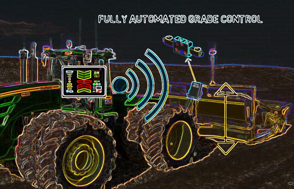
Ditch Assist takes versatility to a new level with our Universal Grade Control. This unique feature, facilitated by a custom-designed PWM valve, ensures precise control of any implement, irrespective of the age, make, or model of your tractor.
Packed with advanced features, Ditch Assist is future-ready. Our system facilitates fully customizable ditch, tile, and plane designs via Slope-IQ, and supports the import of land forming designs, thereby granting you complete control over your projects.
The Ditch Assist system effortlessly integrates with any tractor, regardless of its age, make, or model. With no need for CAN or ISO, it supports any implement including scrapers, ditchers, blades, and levelers. Furthermore, Ditch Assist is GPS-ready and works with any brand, making use of a low-cost RTK or your existing RTK.
Whether you're creating surface drains, leveling land, or installing tile drainage, Ditch Assist offers seamless, fully automated grade control through our PWM valve, with the option of manual operation using a guidance-only kit.
With the innovative Slope-IQ Design Customizer, Ditch Assist lets you personalize the system to suit your specific needs. Add to this the capacity to implement complex land leveling designs using advanced 3D designs in XYZ text format from service providers such as OptiSurface, AgForm3D, and Ezigrade, Ditch Assist truly stands at the forefront of advanced earthworks solutions.
In essence, Ditch Assist provides a comprehensive, user-friendly, and cost-effective automatic machine control system. As you delve into this user manual, you will discover how to leverage the full potential of Ditch Assist to revolutionize your operations and boost efficiency on your farm.
Let's begin this exciting journey to better water management, seamless land forming, and optimal farming operations with Ditch Assist.
To give you a clearer understanding of how Ditch Assist can prove advantageous to you and your operation, let's delve into four typical use case scenarios:
Use Case I: Employing Ditch Assist for Basic Drainage, Grading, and Leveling
Ditch Assist, in its most rudimentary form, functions akin to a laser guidance or control system but with the additional benefits of GPS technology. It's as simple as setting the cutting edge of the implement to the ground at a specific start point, inputting a desired grade, and commencing work from this initial location. Ditch Assist will calculate the necessary target elevation and guide the operator either via on-screen UP/DOWN arrows (using the Guidance Only Kit) or by directly controlling the implement's up/down hydraulics through our PWM valve (with the Full Automation Kit). The use of RTK GPS enables achieving precision equal to laser, minus the need for laser transmitter repositioning and without the influence of environmental conditions on the laser signal.
Ditch Assist can be utilized to construct or apply basic surface or subsurface drains that follow a fairly linear path and don't demand multiple grade breaks along the way. It can also swiftly survey a path by navigating between points A and B and determining the grade. The necessary target elevation is calculated based on the linear distance from the current location to the start point.
When creating level areas like a level pad, you can either input a target grade of zero or specify a target elevation value. Ditch Assist, with the use of high-accuracy GPS (RTK), ensures the implement maintains the same elevation wherever it travels, leading to a flawlessly flat, level surface.
Use Case II: Utilizing Ditch Assist to Craft & Execute Multi Slope Surface & Subsurface Drains
Ditch Assist comes equipped with an advanced feature known as Slope-IQ. It lets users survey a proposed route and design an optimal drain in a similar fashion to most other surface and subsurface drainage grade control systems available. After driving the proposed route in Survey mode to record all points' coordinates and elevations, the operator can employ Slope-IQ to devise a best-fit solution. This maintains a specified minimum grade throughout the route and aligns with the existing topography to follow natural contours where there's adequate slope. This approach reduces the amount of material needing to be moved and maximizes the benefit of the existing terrain.
Slope-IQ also introduces an industry-first advanced Customizer. It enables operators to manually design a fully custom solution based on their target points drawn on the screen, offering complete control over the job. It's a distinctive feature that enables designing subsurface (tile) drainage installations with complete control and flexibility, outpacing systems that don't permit customization of the calculated solution.
By combining the Full Automation Kit, which includes our proprietary PWM valve, with your RTK GPS receiver, Ditch Assist delivers highly accurate grade control, resulting in highly effective drainage with minimal earth displacement.
Use Case III: Using Ditch Assist to Design & Execute Multi Slope Planes on Small Fields or Areas
You can also employ Slope-IQ to create multi slope planes - for example, to landform a small land parcel to ensure all water drains from east to west. In this instance, the design crafted by Slope-IQ is automatically offset at 90 degrees on either side of the original route. You can implement the same design over the entire parcel by surveying down the parcel's center, creating the design, and working outwards from the original survey route. While this method works best in relatively uniform landscapes and is generally suited to smaller areas, users have found it successful for flood irrigation on small fields and for grading small plantation fields to prevent water pooling.
Use Case IV: Using Ditch Assist to Execute Advanced 3D Landforming or Land Leveling Designs Created using Third-Party Software or Services
One of Ditch Assist's popular applications is implementing advanced 3D land leveling or land forming designs from software/service providers like OptiSurface, Topcon’s AgForm3D, and EZ Grade software.
After creating an earthworks design in the chosen software, the design is exported in an XYZ text file format. This file is then loaded into the Ditch Assist App, where it's recognized as a land forming design file and loaded into the grading engine.
Ditch Assist smartly interpolates the original points to fill in the gaps between them based on the surrounding points' values. This results in a highly accurate calculation of the intended design elevation at all locations within the design footprint, regardless of the distance from any given data point. This process also eliminates the problem of larger areas ending up flat where the original point spacing of the design is greater.
As you traverse the field, Ditch Assist continuously calculates the target elevation from the original design and adjusts the implement hydraulics accordingly. Using Ditch Assist in this manner offers an incredible value to benefit ratio as it achieves comparable results to systems costing significantly more - a sentiment echoed by many of our new users!
CAUTIONS, WARNINGS, STATEMENTS
DANGER: Indicates an immediate hazardous situation that, if not avoided, will result in death or serious injury.
WARNING: Indicates a potentially hazardous situation that, if not avoided, could result in death or serious injury.
CAUTION: Indicates a potentially hazardous situation that, if not avoided, may result in injury. It may also be used to alert against unsafe practices.
CAUTION: Indicates specific instructions to avoid accidental loss of data, system configurations settings, or property damage.
IMPORTANT: Indicates specific settings, calibrations, and procedures that must be followed for proper system performance and operation.
Note: Provides informative tips to assist with system setup, calibration, and operation.
Before commencing any operation, it is your responsibility to contact the relevant utility operators to identify underground gas lines, electrical lines, fiber optic or other telephone lines, or any other underground objects in the areas you will be operating. Follow instructions from utility owners regarding working near any buried utilities.

RECOGNIZE SAFETY INFORMATION
• This is a safety-alert symbol. When you see this symbol on your
machine or in this manual, be alert to the potential for personal injury.
• Follow recommended precautions and safe operating practices.
FOLLOW SAFETY INSTRUCTIONS

• Carefully read all safety messages in this manual and on your
machine safety signs. Keep safety signs in good condition. Replace missing or damaged safety signs. Be sure new equipment components and repair parts include the current safety signs. Replacement safety signs are available from your dealer.
- Learn how to operate the machine and how to use controls properly. Do not let anyone operate without instruction.
- Keep your machine in proper working condition as specified by the manufacturer.
- If you do not understand any part of this manual and need assistance, contact your dealer.
REMOVE PAINT BEFORE WELDING OR HEATING
- Avoid potentially toxic fumes and dust.
- Hazardous fumes can be generated when paint is heated by welding, soldering, or using a torch.
- Remove paint before heating:
- Remove paint a minimum of 100 mm (4 in.) from the area to be affected by heating. If paint cannot be removed, wear an approved respirator before heating or welding.
- If you sand or grind paint, avoid breathing the dust. Wear an approved respirator.
- If you use solvent or paint stripper, remove stripper with soap and water before welding. Remove solvent or paint stripper containers and other flammable material from area. Allow fumes to disperse at least 15 minutes before welding or heating.
- Do not use a chlorinated solvent in areas where welding will take place.
- Do all work in an area that is well ventilated to carry toxic fumes and dust away.
- Dispose of paint and solvent properly.

AVOID HIGH-PRESSURE FLUIDS
- Escaping fluid under pressure can penetrate the skin causing serious injury.
- Avoid the hazard by relieving pressure before disconnecting hydraulic or other lines. Tighten all connections before applying pressure.
- Search for leaks with a piece of cardboard. Protect hands and body from high pressure fluids.
- If an accident occurs, see a doctor immediately. Any fluid injected into the skin must be surgically removed within a few hours or gangrene may result. Doctors unfamiliar with this type of injury should reference a knowledgeable medical source.
CHECK HOSES FOR DAMAGE
- Hydraulic hoses can fail due to physical damage, kinks, age and exposure.
- Check hoses regularly.
- Replace damaged hoses.
Ditch Assist Control Module
Contains Transmitter Module FCC ID: QOQWF121
Contains Transmitter Module IC: 5123A-BGTWF121
Certifications
Compliant to the following specifications:
CE
WF121 is in conformity with the essential requirements and other relevant requirements of the R&TTE Directive (1999/5/EC). The product is conformity with the following standards and/or normative documents.
EMC (immunity only) EN 301 489-17 V.1.3.2 in accordance with EN 301 489-1 V1.8.1
Radiated emissions EN 300 328 V1.8.1
FCC and IC
This device complies with Part 15 of the FCC Rules. Operation is subject to the following two conditions:
(1) this device may not cause harmful interference, and
(2) this device must accept any interference received, including interference that may cause undesired operation.
FCC RF Radiation Exposure Statement:
This equipment complies with FCC radiation exposure limits set forth for an uncontrolled environment. End users must follow the specific operating instructions for satisfying RF exposure compliance. This transmitter must not be co-located or operating in conjunction with any other antenna or transmitter. This transmitter is considered as mobile device and should not be used closer than 20 cm from a human body.
IC Statements:
This device complies with Industry Canada license-exempt RSS standard(s). Operation is subject to the following two conditions: (1) this device may not cause interference, and (2) this device must accept any interference, including interference that may cause undesired operation of the device.
To Comply with FCC and Industry Canada RF radiation exposure limits for general population, the antenna(s) used for this transmitter must be installed such that a minimum separate distance of 20cm is maintained between the radiator (antenna) and all persons at all times and must not be collocated or operating in conjunction with any other antenna or transmitter.
| Software End User License Agreement |
| End User License Agreement This End User License Agreement (the "Agreement") is made between Northern Plains Drainage Systems Ltd (the "Vendor") and the user (the "Licensee"). Under this Agreement, the Vendor grants the Licensee a non-exclusive and non-transferable license (the "License") to use Ditch Assist Software, which comprises both the mobile (Android) application and proprietary operating software that is run on the Ditch Assist Control Module (collectively referred to as the "Software"). The Software, including all of its components, the user interface, and any accompanying printed, electronic and online documentation remain the exclusive property of the Vendor. Intellectual property rights, including copyright, and distribution rights of the Software are retained solely by the Vendor. This Agreement is strictly a license for use and does not transfer any ownership rights of the Software to the Licensee. The Licensee agrees not to modify, reverse-engineer, or decompile the Software through any currently available or future technology. Any violation of these terms will be considered a substantial breach of this Agreement and may result in its termination. The initial purchase price paid by the Licensee for the Software will cover the entire license fee. The fee is inclusive of the Software's functionalities as of the time of purchase. If the Vendor introduces new features in the future that result in an increase in the price of the Software, the Vendor may offer the Licensee an opportunity to access these features as an upgrade for an additional cost. The Software is provided "as is". The Vendor assumes no liability for any direct, indirect, incidental or consequential damages that the Licensee may suffer due to the use or failure to use the Software. This includes, but is not limited to, loss of profits, loss of production, loss of data or any other business or economic losses. The Vendor does not guarantee that the Software will be fit for the Licensee's particular purpose or requirements, or that its use will be uninterrupted or error-free. The Licensee acknowledges that software, in general, may have bugs or flaws within an industry-accepted level. The Agreement will be valid from the time the Licensee installs the Software and will continue indefinitely unless terminated. The Agreement may be terminated if the Licensee fails to comply with any of its terms. In the event of unforeseen and uncontrollable occurrences such as natural disasters, war, or any other force majeure event, the Vendor will not be held liable for failing to fulfill its obligations under this Agreement, provided that the Vendor has taken all reasonable measures to mitigate the impact of such events. The Licensee recognizes that external factors beyond the Vendor's control, such as the accuracy of GPS signals, satellite interference and outages, or the performance of hydraulic systems on which Ditch Assist is installed, may influence the operation of Ditch Assist. The Vendor will not be held responsible or liable for any such occurrences. This Agreement will be governed by the laws of the Province of Manitoba and will be enforced or construed in accordance with these laws. Both parties agree to submit to the jurisdiction of the courts of the Province of Manitoba for any disputes or enforcement arising from this Agreement. The Vendor commits to providing updates and maintaining the Software to remain compatible with future hardware and Android OS releases as per industry standards. However, the Vendor cannot guarantee that the Software will always be compatible with all future hardware and Android OS releases, and the Vendor will not be held responsible or liable for any losses or damages resulting from such incompatibility. This Agreement is the complete agreement between the Vendor and the Licensee, superseding all prior agreements or representations, whether written or verbal. Any modifications to this Agreement must be made in writing and signed by both parties. The Vendor's successors and assigns are bound by the terms of this Agreement. All notifications to the Vendor under this Agreement should be sent to the following address: Northern Plains Drainage Systems Ltd, Box 9, Elm Creek, Manitoba, R0G 0N0, Canada. |
| Hardware Warranty InformationThe Vendor guarantees that for a duration of 12 months from the "Warranty Start Date" (defined as the date Ditch Assist is bought from the Vendor or an Authorized Dealer of the Vendor), all hardware components will be free from defects in materials and workmanship when used normally, in accordance with the product's intended usage and installation. In the event of any hardware failure during normal operation within the 12-month warranty period from the "Warranty Start Date", the Vendor commits to repairing or replacing the faulty hardware component at no cost to the Licensee. No additional express or implied warranties are offered by the Vendor. The sole remedy for breaching this express warranty is the repair or replacement of the faulty product. THE VENDOR EXPRESSLY DISCLAIMS ANY IMPLIED WARRANTIES OF MERCHANTABILITY AND FITNESS FOR A PARTICULAR PURPOSE. The Vendor does not provide a warranty for damages caused by misuse, alterations, negligence, accidents, vandalism, natural disasters, incorrect installation, improper storage, or any other event outside the normal, intended use and installation of the system. The Vendor retains the right to repair products that malfunction within the warranty period, particularly when a product failure is reported after successful installation and usage for its intended purpose for any duration of time. The Vendor may require malfunctioning products within the warranty period to be returned for assessment. Products that have been repaired, rebuilt, or replaced will have a warranty for the remaining duration of the original product warranty. Any original product or product components replaced during repair, rebuilding, or replacement will be retained by the Vendor. All software and firmware developed and/or provided by the Vendor is sub-licensed "as is". The Vendor will not be held responsible for any direct, indirect, incidental, or consequential damages, including data loss, resulting from the usage of software and firmware provided by the Vendor. |
Getting Started with Ditch Assist
Ditch Assist Required Components
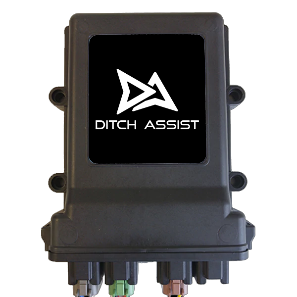 | Ditch Assist Control ModuleThe Control Module is the central nexus of the Ditch Assist system, linking all components together. It not only powers the GPS receiver but also gathers and processes incoming GPS messages. Additionally, it facilitates wireless transmission and reception of information to and from the Ditch Assist Android app. Furthermore, it smartly manages the proportional valve for automated control when the valve is in use. The Control Module is designed with an environmentally sealed casing rated IP67, ensuring its robustness in a wide range of operating temperatures from -40°C to +85°C. It is compatible with both 12V and 24V systems, and operates efficiently across a voltage range of 9V to 32V. This module supports communications via CAN bus and RS232 protocols, and also features Wi-Fi wireless capability, adding an extra layer of connectivity and ease of use. |
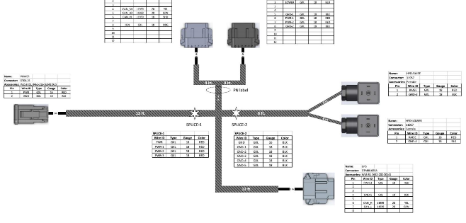 | Ditch Assist Main HarnessThis crucial component comes with a detachable power harness, providing the convenience of permanent installation or the flexibility to install multiple power harnesses on various tractors as needed. It interfaces seamlessly with the Control Module, coordinating with both the GPS and the proportional valve. In addition, it includes a connector specifically designed for a GPS breakout, permitting the connection of brand-specific GPS cables. |
| GPS Breakout HarnessHarness tailored to your specific brand enables seamless connection and power supply to your GPS receiver. We provide GPS harnesses compatible with most widely-used agricultural GPS receivers and Emlid, ensuring a broad range of compatibility. In addition, we offer a DB9 cable to interface with numerous other devices using manufacturer-specific breakout harnesses. These harnesses include a DB9 connector designed to relay GPS messages to third-party devices. | |
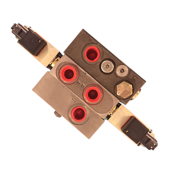 | Pulse Width Modulation (PWM) Hydraulic Valve (included in full automation kit) For automated hydraulic control, a PWM hydraulic valve is essential. The official valves provided with Ditch Assist are custom-assembled exclusively for use with our system. Only valves offered by our authorized dealers should be used. Please note that no support or warranty will be extended if alternative valves are utilized. Note that exact valve model and configuration may vary depending on geographic location and your equipment. Our proportional valve comes standard with hydraulic couplings and hoses to facilitate connection of your implement's up/down hydraulic hoses to the valve, and subsequently, the valve to the tractor remotes. Valves can be adjusted to either open or closed center configurations, enhancing their adaptability to various system requirements. |
| Valve Bypass KitThe valve bypass kit lets you integrate two extra lines into the tractor's remotes, giving you the ability to circumvent the valve when necessary. This function can prove beneficial when there's a need for exclusively manual control, or for swiftly switching to manual control without resorting to the manual raise/lower buttons on the application interface. Consequently, there's no need to disconnect the valve. | |
 | Ditch Assist AppThe Ditch Assist App, a key component of the system, provides an intuitive user-interface for system operation. This Android application can be easily downloaded for free from the Play Store, by simply searching for "Ditch Assist". Updates to the app are regularly published on the Play Store, facilitating seamless installation. For your convenience, we also provide access to the current version of the app, as well as legacy and current beta versions, on the App Releases page of the Ditch Assist website. You can visit https://www.ditchassist.com/app-releases/ to access these versions. |
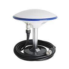 | GNSS (GPS) AntennaDitch Assist is compatible with a wide range of popular GNSS equipment, giving you the flexibility to integrate it with your existing technology. Alternatively, you may have acquired Ditch Assist bundled with a compatible GNSS system from your dealer. The GNSS antenna, which is mounted on the implement being controlled, delivers necessary NMEA position messages to the Ditch Assist Control Module. This process ensures precise operation and coordination within your system. |
 | Android TabletThe Ditch Assist App is specifically designed to operate on 10" Android tablets that have a recent version of the Android operating system. While it's possible to run the app on phones and smaller tablets, you may encounter issues with resizing, layout, possible crashes, and missing features. Thus, we strongly recommend using a 10" or larger screen tablet from a recognized manufacturer. Some budget-friendly units available in the market may compromise on the quality of components like Wi-Fi transmitters and available memory resources, potentially leading to sub-optimal performance. Our current tablet recommendation is the Samsung Galaxy Tab S6 Lite. While the app is functional on other devices and various screen resolutions, the layout may not align as intended. Buttons and info windows might not appear in their designated locations on the screen, affecting the user experience. |
Quick-Start Guide to Using Ditch Assist
While we strongly advise reading the entire manual for the best user experience, if you're in a hurry, here are the key steps to get Ditch Assist up and running as swiftly as possible:
- Install Ditch Assist Hardware:
- Connect the Power Harness directly to the tractor battery terminals
- Please refrain from connecting it to a trailer power connector or an in-cab power strip.
- Position the Ditch Assist Control Module
- Attach the module on the implement using the provided magnet mounts, ensuring a clear line-of-sight between the module and the cab.
- Position the PWM Valve
- Install the PWM valve on the implement or the rear of the tractor using the supplied bracket, or you may fabricate a custom mounting bracket if preferred.
- Set Up the RTK GNSS Antenna
- Attach the antenna on the implement at a location that moves up and down with the blade or cutting point.
- The antenna should have an unobstructed view of the sky from all operating positions from 10 degrees above the horizon.
- Configure GNSS Settings
- Set the GNSS to output GGA and VTG messages at 5Hz or 10Hz, with a baud rate of 38,400.
- Connect Components
- Use the Ditch Assist harnesses to connect all parts.
- Connect Power Cable: Attach the power cable to the main harness.
- Connect GNSS: Use the GPS-specific cable for your device to connect GNSS to the main harness.
- Connect Hydraulic Raise and Lower Connectors: Attach these to the solenoids on the PWM valve (direction is not crucial at this point).
- Connect Main Harness: Attach the main harness to the Ditch Assist Control Module (connectors will only fit into their corresponding ports on the controller).
- Protect the Control Module: Use the provided plug connectors to seal the two empty ports on the Ditch Assist Control Module. This step is important to prevent dirt and moisture from damaging the controller electronics.
- Use the Ditch Assist harnesses to connect all parts.
- Connect the Power Harness directly to the tractor battery terminals
- Connect Tablet to Ditch Assist Control Module
- Ensure that the Control Module is switched ON - you should see the LED lights glowing on the module.
- Download and install the Ditch Assist App onto your tablet.
- Go to your tablet's wi-fi settings and search for a wi-fi network name that starts with DitchAssist.
- Connect your tablet to the DitchAssist wi-fi network using the password 12345678.
- If your tablet alerts you about the network lacking an internet connection, select the option to continue with the connection.
- Open the Ditch Assist app. Tap Connect WiFi. Confirm that you're connected to the Ditch Assist Control Module. This can be confirmed via the Status details on the upper left corner of the screen (it should state that you're connected to DitchAssistxxxx, with xxxx representing the unit's serial number).
- Ensure that the GNSS info panel is filled - it should display details about your current positional coordinates, number of satellites, fix status, etc. If this panel remains empty, refer to the GNSS settings and troubleshooting parts of this user manual.
- Verify Implement Hydraulic Control from the Ditch Assist App
- Identify the hydraulic remotes that are connected to both the bypass and the valve - manipulating the bypass controls will result in the implement's elevation and depression.
- Adjust the valve hydraulics to detent mode, which allows for a steady flow.
- On the Ditch Assist App, access the Grading screen by tapping on the Grading tab button.
- Press and maintain the Implement Raise and Lower buttons on the tablet screen - the implement should correspondingly rise and descend.
- If pressing the raise button results in the implement lowering, switch the cable connections to the valve solenoids. Then, retest to confirm the correct operation direction.
- Begin Operating (see appropriate chapters for information)
- Run a survey and then use Slope-IQ to design a best-fit or customized drain profile, or
- Import a 3D landforming design from your desktop software, or
- Enter a straight grade or target elevation to perform simple grading or leveling
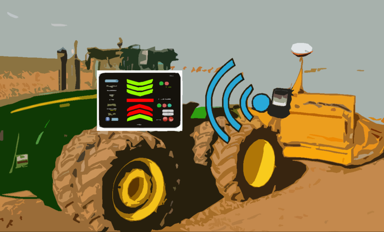
Ditch Assist Operating Principles
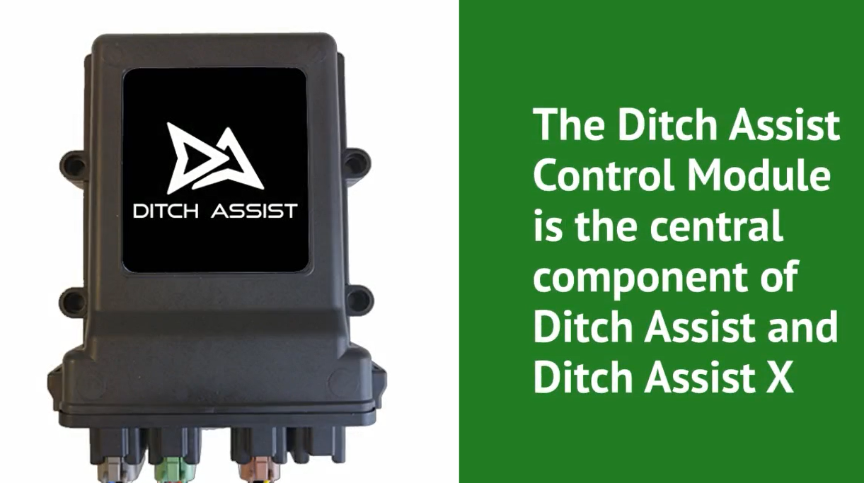
The Ditch Assist Control Module is the central component of the Ditch Assist system
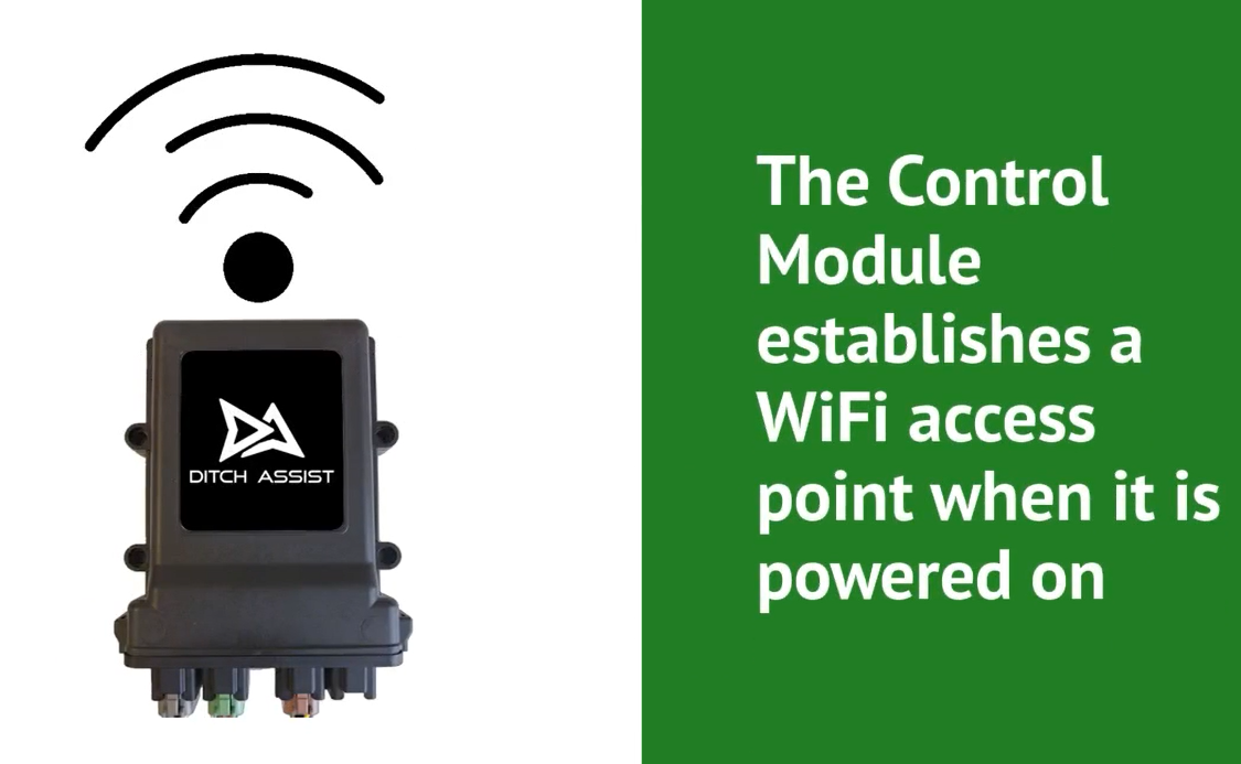
The Control Module establishes its own WiFi access point when it is powered on
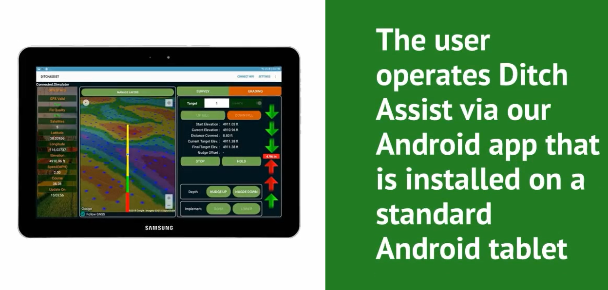
The user operates Ditch Assist via the Ditch Assist Android App that is installed on an Android tablet
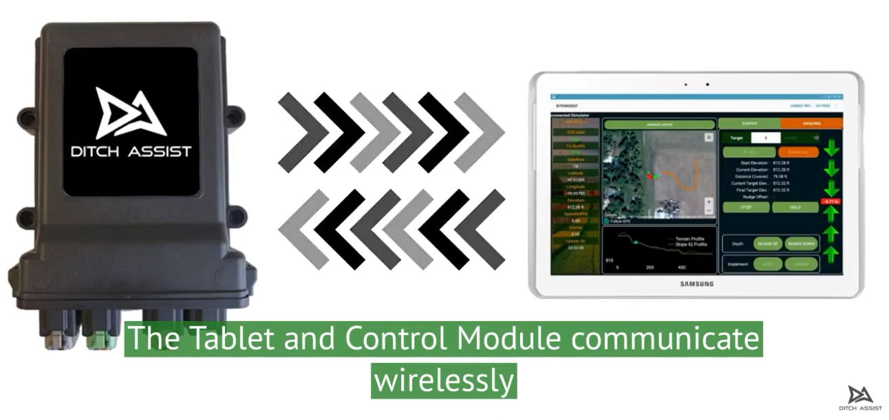
The tablet and Control Module communicate wirelessly via WiFi
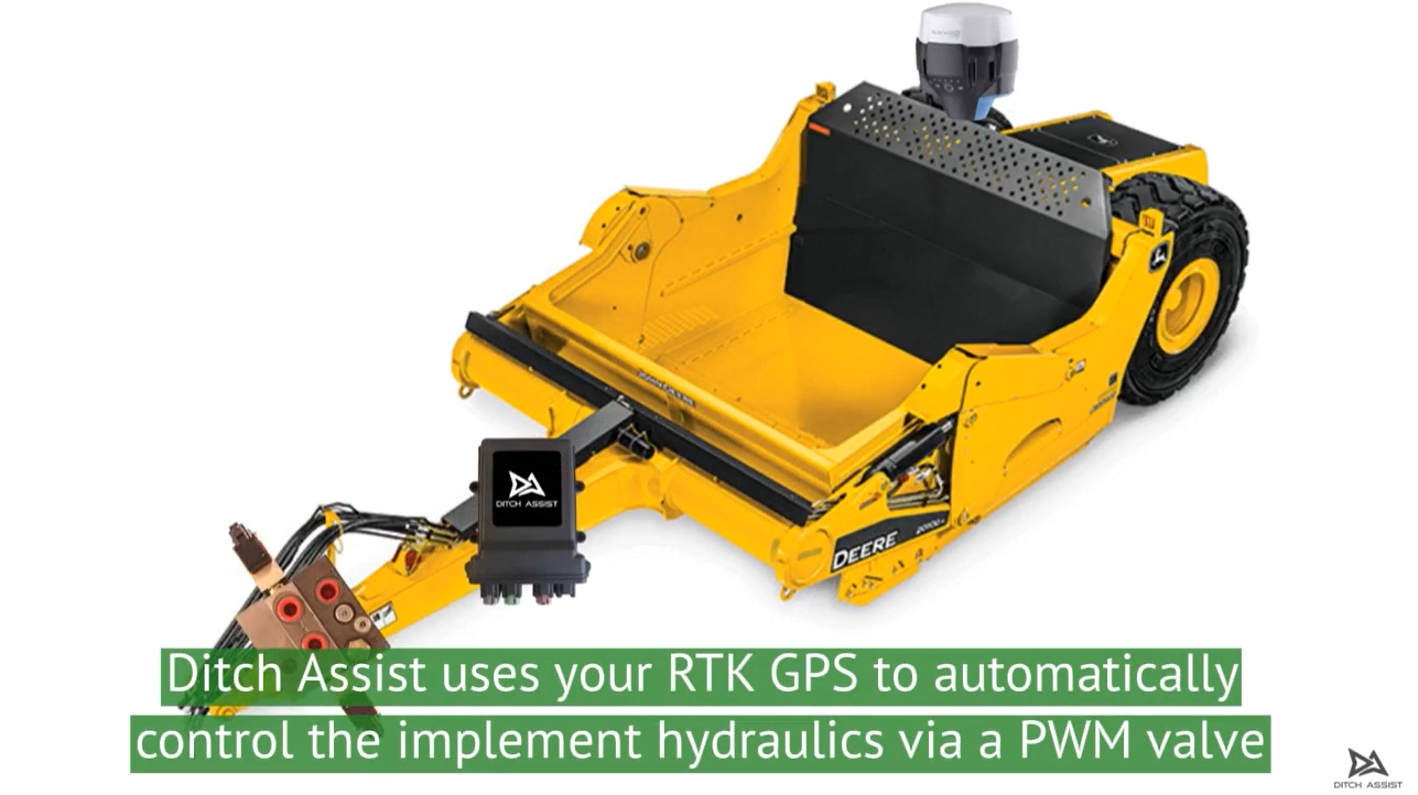
Ditch Assist uses the data fed from a RTK GNSS receiver to automatically adjust the implement height via a PWM hydraulic valve
Typical Installation
The Ditch Assist Control Module and proportional valve (if used) are mounted either near the hitch on the implement being controlled, or at the rear of the tractor. The power harness is connected directly to the tractor battery. The GPS antenna is mounted in a raised position on the implement being controlled, and is mounted to a location that moves up and down proportionally to the cutting edge.
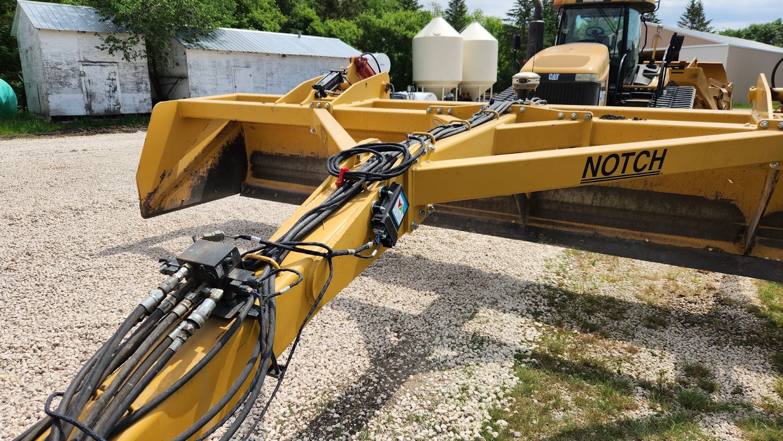
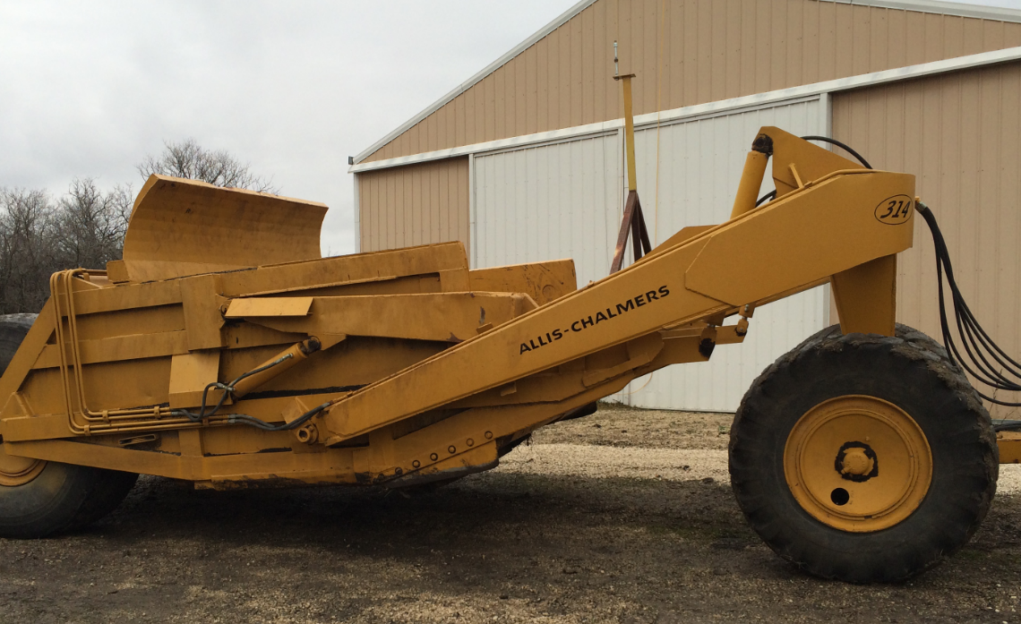
A common setup for a land leveler or similar implement with a straight blade involves mounting the PWM valve on the implement tongue, a few feet away from the hitch point. The Ditch Assist Control Module is attached to the tongue or any other suitable spot, using either the magnetic mounts or a custom-made bracket. The GNSS receiver is placed at the top of the implement. Please note that you may need a raised mount if the implement has components that overhang or for shorter implements that might obstruct the GNSS's view of the sky due to the tractor.
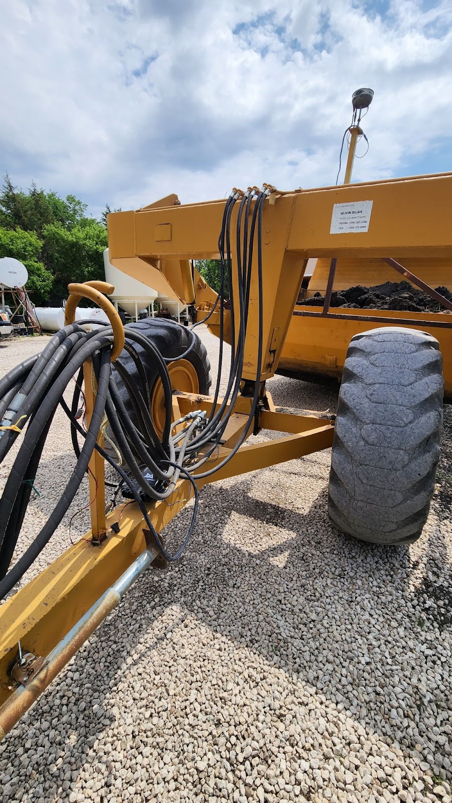
In a typical configuration for a pull-type scraper, the valve is installed on the tongue using either the provided or a custom bracket, with the Ditch Assist Control Module also mounted on the tongue. Please note that in this specific setup, if there are any WiFi connectivity issues, the Ditch Assist Control Module can alternatively be installed on the vertical part of the scraper frame (for instance, near the white label), as this would provide a better line of sight to the tractor cab.
For a scraper, it's essential that the GNSS is mounted in a manner that allows it to move proportionately to the cutting edge. This generally necessitates a mast to keep it above the metal components surrounding it when the scraper is in its maximum lowered position.
Understanding How Ditch Assist Works
- Ditch Assist's primary function is to sustain a target elevation with the implement blade. This target elevation can be derived from one of the following: a 'best-fit' design generated through Slope-IQ, which is based on a survey and operator input; a pre-established land leveling design created in third-party software and loaded into the Ditch Assist app; or a straightforward target grounded on a specified elevation (for instance, when leveling an area to a particular elevation), or on a grade plane depending on a starting elevation.
- The Ditch Assist Control Module obtains GPS location data from the GPS system. This information is then wirelessly transmitted to the Android device that is operating the Ditch Assist App.
- Based on the current location, the Ditch Assist app determines the target elevation for that point. It then conveys this information to the Control Module.
- The Control Module compares the intended elevation with the actual one, thus establishing the required response - that is, deciding whether the implement needs to be elevated or lowered to achieve the desired level. This adjustment is initiated by activating the solenoids of the PWM valve, leading to vertical movement. Due to the continuous motion of the vehicle and implement, coupled with minor fluctuations even with RTK, precisely attaining the target is almost unachievable. This results in a constant cycle of minute adjustments, fluctuating between raising and lowering, in an effort to reach the target. While subtle movements might go unnoticed, more significant variances will lead to noticeable changes in the hydraulic cylinders' positions to modify the implement's height.
Important GNSS (GPS) Limitations to Understand
Ditch Assist heavily relies on precise GNSS (Global Navigation Satellite System) information. A lack of high-accuracy positioning data can result in less than optimal performance.
1. Non-RTK GNSS: Standard GNSS systems like GPS, without the added precision of Real-Time Kinematics (RTK), can have position errors up to several meters. For a system like Ditch Assist, which requires centimeter-level precision, this can lead to inaccuracies in the alignment and leveling of the land. For instance, a non-RTK GNSS might cause the implement to be moved when it's not necessary, or it might fail to signal when the implement does need to be moved, leading to uneven terrain.
2. Performance Issues with RTK: While RTK provides more precise positioning data than standard GNSS, it isn't immune to performance issues. RTK requires a stable communication link between the base station and the receiver, and disruptions to this link can result in temporary loss of RTK's centimeter-level precision. For instance, if the radio link fails or the base station loses its own GNSS signal, the receiver might switch back to standard GNSS accuracy until the issue is resolved. This can result in similar inaccuracies to those experienced with non-RTK GNSS.
3. Multipath Errors: Both non-RTK GNSS and RTK can be affected by multipath errors, which occur when satellite signals are reflected off nearby objects before reaching the receiver. These reflected signals can confuse the receiver, leading to incorrect position calculations. In the context of Ditch Assist, this could mean incorrect implement adjustments.
4. GNSS Signal Blockage: This can be a problem in areas with tall trees, buildings, or other obstacles that might block the line of sight to the GNSS satellites. The loss of signals from some satellites can decrease the accuracy of the position calculations. For Ditch Assist, this could again lead to errors in implement movement.
The use of RTK GNSS technology can mitigate some of these issues, providing higher accuracy for precision agriculture applications like Ditch Assist. However, users should still be aware of potential sources of error and work to minimize them for the best performance.
Installation Instructions
Depending upon the type of equipment you plan to install Ditch Assist on, the exact method will vary somewhat. Ditch Assist is extremely simple to install and move between equipment. The following guidelines should help you determine a suitable installation for your particular equipment.
IMPORTANT: Make sure that Ditch Assist components are installed so that parts, cables and hoses will not be stretched, pinched, or otherwise damaged during the operation of equipment. Keep in mind that cables and hoses may be subject to stretching when the implement is turning, and that components mounted near the hitch or rear of the tractor may come into contact with other parts when cornering.
Proportional Valve Setup
The specific PWM valve included with your kit will depend upon your country and market availability at the time of purchase. Consult the specific installation instructions that should be included in your installation kit - if these are missing please contact your dealer to obtain them. Ensure you assemble the hydraulic components as shown. Below are common hydraulic assembly instructions for our Bucher and Rexroth valves (other valves may be slightly different, and your dealer will provide specific instructions if different from those below):
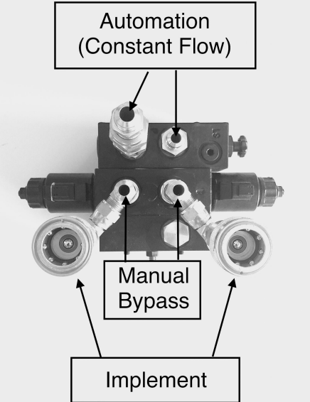
For the Bucher valve, the automation hoses necessary for constant flow should be connected to the external valve block (the block that has the dial). Meanwhile, the fittings for the manual bypass and implement hoses should be attached to the central block, which is situated between the solenoids.
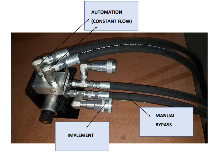
For the Rexroth valve, the hydraulic hoses needed for automation (providing a constant flow) should be connected to the ports located on the valve block's top surface. Meanwhile, the implement connectors and manual bypass fittings should be attached to the ports situated on the valve's side.
Control Module & Valve Installation
Ensure that the Control Module is securely installed either at the implement's front, near the hitch, or at the tractor's rear, with minimal obstructions to the line of sight to the cab. The included magnetic mount can be used for this purpose, or you can fabricate your own if needed. The Control Module can be installed in either a horizontal or vertical orientation.
IMPORTANT: While the Control Module is sealed against weather, and all connectors that plug into it come with waterproof gaskets, we strongly advise installing it with the ports facing downward to prevent water from accumulating in and around them. If the wiring harness connectors are removed from the Control Module, this might allow moisture to infiltrate. Always ensure all port connectors or covers are in place when leaving the Control Module outside.
Position the proportional valve in a place that allows the implement hydraulic hoses to connect to it, and enables the included hoses you attached to the valve to reach the remote ports at the tractor's rear. To prevent damage during operation, the valve must be securely installed. If the provided angle iron mount is used, the pre-drilled holes will align with the valve's mounting holes, and the mounting plate should be either bolted or welded to the equipment.
SUGGESTION: If you intend to use Ditch Assist with multiple different implements, consider permanently mounting the valve on your tractor, as it may be more practical.
Example Mounting Setup on a Scraper or Land Leveler
Valve bracket should be mounted securely to the implement. Do not weld the bracket with the valve mounted. Remove the module before welding anything to the implement. Make sure the module is mounted where it will not be dislodged by debris, moving parts, or hydraulic lines. Secure all cables and hydraulic lines so they will not be pinched, stretched or damaged during operation.
Connecting the Hydraulic Hoses
The two hoses coming from the P and T ports on the valve, in addition to the hoses for the bypass, need to be connected to the tractor - a total of four hoses. The hydraulic remotes on the tractor that Ditch Assist is connected to should be set to a continuous flow, allowing the valve to raise and lower the implement as required. Depending on the age and size of your tractor, you might need to adjust the flow rate if you observe that the implement is moving up or down too quickly or too slowly. The App also contains settings for valve response - refer to the Settings Menu for more details.
Connecting the Wiring Harness to the Valve
Attach the two plugs from the harness to the connectors on the proportional valve. You might need to swap the connectors later if you notice that the manual up/down controls in the App are functioning in reverse. Specifically, if manually lowering the implement in the App causes it to lift, you'll need to switch the wired connectors on the valve. Refer to the Quick Start guide at the beginning of the manual to understand the process for determining this.
Wiring Harness Installation
The two large Deutsch connectors on the main harness should be plugged into ports A and C of the Ditch Assist Control Module. Each connector has a distinct 'key', ensuring that it's impossible to make incorrect connections. Ports B and D should be left vacant and sealed with the included dust plugs for protection.
Link the power harness directly to the tractor battery terminals and route the cable back to the main harness. Connect it to the power connector on the main harness (it can only fit into one connector, so it's not possible to make an incorrect connection). Make sure to connect the power harness exclusively to the vehicle battery. One of the most frequent troubleshooting issues we encounter is due to the power coming from a trailer plug or an in-cab power strip, which either cannot supply sufficient current to the solenoids or is prone to power surges that cause problems with the microcontrollers.
Finally, connect the GPS breakout cable to the remaining open connector on the harness and route it to the GPS antenna location.
Any slack or excess cables should be secured using ties or other suitable means to prevent them from becoming damaged during machine operation.
GPS Information
Ditch Assist was developed with compatibility in mind, designed to work with a wide range of GPS brands and models. We support both the NMEA 2000 message standard, which is a CAN-based communication protocol, as well as the NMEA 0183, a standard associated with 'serial port' communication.
GPS Requirements and Settings for Ditch Assist
NMEA Output Settings Required
You should configure your GPS to emit the following NMEA messages:
- SET BAUD RATE TO 38,400
- GGA MESSAGE AT 10Hz (5Hz if 10Hz is not available)
- VTG MESSAGE AT 10Hz (5Hz if 10Hz is not available)
- DISABLE ALL OTHER MESSAGES IF POSSIBLE
(If you can't designate a specific message rate for each message, or cannot disable messages that are not required, then enable 5Hz rate for all messages.)
Diagnosing GPS/GNSS Connectivity using the Status 1 and Status 2 LEDs on the Control Module
- The Status 1 light blinks when a valid CAN NMEA 2000 GPS message is received. If you are connecting a GNSS receiver such as an Outback Smart Antenna, we typically expect to see this light begin to blink once the receiver is powered on and has established its position.
- The Status 2 light blinks when a valid RS232 NMEA 0183 GPS message is received. Most GPS connected to Ditch Assist will be using this format, so the Status 2 light is a critical indicator that the correct messages and rates are enabled - if the Status 2 light does not flash this means the Control Module is not receiving valid messages.
- The blinking pattern of both Status 1 and Status 2 LEDs mirrors the frequency of the message rate. Simply put, a consistent blink every second signifies a 1Hz message rate, implying that the GPS updates the position every second. For peak performance, it is advisable to have a message rate of at least 5Hz, with 10Hz being more desirable. A slowly flashing Status 1 or Status 2 light (e.g. flashing once every few seconds) could signify that the message rate might not be set adequately fast, leading to potential problems. For instance, the blade might bypass the target before receiving a new position, resulting in a 'bunnyhopping' effect as the system constantly tries to correct the previous overshoot. This might cause your implement to perform a continuous dance-like display. If you notice the Status 1 or Status 2 light blinking very quickly, then stopping, then flashing quickly again, this can be an indication that the message rate is too fast for the GPS receiver to output and a ‘bottleneck’ has formed. In this case, try turning the message rates down, e.g. from 10Hz to 5Hz
How to Configure John Deere Smart Antennas
When utilizing a John Deere smart antenna with Ditch Assist, the Ditch Assist GPS cable will provide power to the unit and directly extract the necessary position information into the Control Module. In this setup, there is no need to connect the GPS to the tractor or the GreenStar Display. It is essential to configure the receiver while it is connected to the John Deere CAN system, such as when it is installed on the tractor's roof. Once properly configured, you can remove the receiver and attach it to the implement, connecting it to the Ditch Assist Control Module using the appropriate cable. Ditch Assist will supply power to the receiver and retrieve the required GPS messages from it.
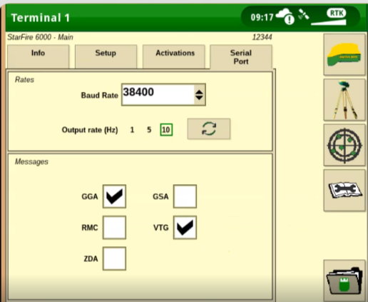
- First, scroll through the main screens to the StarFire screen.
- Next, tap on the icon that looks like a StarFire receiver.
- Open the Serial Port tab.
- Use the dropdown to set the baud rate to 38,400.
- Adjust the output rate to 5Hz or 10Hz. Note that some receivers will not have 10Hz enabled if it hasn't been activated. So in this case 5Hz should be fine.
- Finally, turn on the GGA and VTG message. Turn off any others that may be on.
- Exit the menu once the changes are complete.
- Your receiver should now be broadcasting the selected NMEA strings. Connect it to the Ditch Assist Control Module and verify that the Status 2 light on the module begins to flash as this indicates that GPS data are being received
How to Configure Trimble/Case IH GNSS Receivers
To enable NMEA messages on Trimble/Case-IH GPS receivers, you can follow these general steps:
For Trimble systems using a NAV II or NAV III Controller:
On these setups, a good option is to use the DB9 serial cable on the Nav Controller harness to connect to our generic DB9 GPS Cable. Note here that the GPS cable will need to run into the tractor cab to connect to the Nav harness.
- On a Trimble display running precision IQ, go into the GNSS settings.
- Open the NMEA Messaging tab and turn messaging on.
- Tap on message rate and set it to either 5Hz or 10Hz. Choose the fastest option available.
- Next, select Autopilot as the output port.
- Note that if a TM 200 is present, you cannot use it's Port A to output because this port is actually in use by the Nav controller, even though it gives you the option to select it!
- For an Autopilot connected to a Pro 700 or Intelliview 4 display, the process is similar.
- Open the Nav Settings, and click Edit under the NMEA Output Setup.
- Turn NMEA output on, and confirm that the Baud Rate is set to 38,400.
- The speed setting here aren't relevant for Ditch Assist so you can leave it off.
- Make sure the Precision and Accuracy settings are set to 8, for the reasons we mentioned previously.
- Return to the settings menu, and open the NMEA Message Settings. Here, you'll need to enable GGA and VTG at either 10Hz, or 5Hz if 10 isn't available.
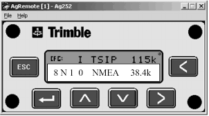
For a Trimble 372 receiver, the easiest method is to use RDI on the Pro 700, or Ag Remote on Trimble displays. Usually you’ll program Port A or C (assuming Port B is connected to the RTK radio), but this may differ with specific configurations.
- On the RDI or Ag Remote screen, press the right arrow twice or until you reach the Configuration option
- Press Down to enter the Configuration Menu
- Scroll to the Port you need to configure
- Set the position output to NMEA (it likely says TSIP currently), and make sure the baud rate is set to 38,400.
- You should see a line that shows something like 8N1 NMEA 38k.4 when correctly configured
- Scroll down again to locate the entry for NMEA1
- Make sure GGA is capitalized here, and that all other messages are in lower case
- Scroll down again to NMEA2
- Make sure VTG is capitalized here and all others are off
- Locate the setting for NMEA OUT and set it to ASAP - this should get you 5Hz updates
How to Configure Emlid RS2 and RS3 Receivers
To enable NMEA messages on the Emlid RS2 GNSS receiver, you can follow these steps:
- Connect to the RS2 GNSS receiver using the ReachView app on your mobile device or web browser.
- Open the ReachView app and navigate to the "GNSS Settings" or "RTK Settings" section.
- Look for the option related to NMEA messages or NMEA output. The specific location may vary depending on the version of ReachView, but it is usually found within the GNSS or RTK settings.
- Enable or toggle the NMEA messages option. You have the option to select specific NMEA message types or configure the message rate.
- Set the baud rate to 38,400
- Save the changes or apply the settings.
- The RS2 GNSS receiver will now output the selected NMEA messages according to the configured settings.
How to Configure Outback GPS Receivers
Many Outback GPS smart antennas are plug-and-play and will provide the required GPS messages over CAN bus automatically when connected to Ditch Assist with our Outback GPS harness. If your Outback antenna has a small circular connector then it likely falls into this category. Otherwise, to manually enable NMEA messages on Outback GPS receivers, you can follow these general steps:
- Access the GPS receiver's menu or settings. This is typically done through a display or user interface on the device.
- Look for a section related to communication settings or NMEA output configuration.
- Within the communication settings, you should find an option to enable NMEA messages or configure the NMEA output.
- Enable the NMEA output or select the desired NMEA message types you want to receive.
- Check if there are additional settings to adjust the baud rate and message rate (such as 10Hz or 5Hz).
- Save the changes and exit the menu or settings.
Please note that specific steps may vary depending on the model and firmware version of your Outback GPS receiver. It is recommended to refer to the user manual or consult the manufacturer's documentation for precise instructions related to your specific model.
GPS Corrections and Accuracy
Ditch Assist relies on a precise GPS signal for optimal performance. If your GPS lacks accuracy, it may impact the performance of Ditch Assist.
IMPORTANT: If you are not using RTK with your own base station, we highly recommend using a subscription-based correction service with a published vertical accuracy of at worst 2-3 inches as a minimum requirement. It is possible that you may find the GPS accuracy provided by your current system to be insufficient. This is not a fault of Ditch Assist, as it simply processes the incoming GPS data it receives.
Ditch Assist is not compatible with low-accuracy correction signals like WAAS or low-accuracy SBAS corrections such as SF1 or OmniSTAR L1. We recommend, at a minimum, utilizing a subscription-based dual-frequency (L1/L2) satellite-delivered correction signal.
Below are specifications for the recommended GPS corrections:
USE WITH CAUTION:
Subscription-based L1/L2 correction services like SF2, SF3, CenterPoint RTX, TerraStar, or Atlas are NOT RTK accurate. Expect fluctuations in elevation readings with these systems (e.g., the machine may experience up/down movements even when stationary). Not recommended for use in flat fields or for land leveling or tiling. The respective manufacturers do not endorse these corrections for vertical accuracy, and you will have no recourse in the event performance is not acceptable.
SHOULD BE OKAY UNDER MOST CIRCUMSTANCES:
Network RTK Correction through CORS, Cellular, or Long Range Radio link to a remote base station (e.g. on a nearby equipment dealers’ rooftop). These corrections typically provide good accuracy for surface grading. Keep in mind that the closer you are to the base station, the better the repeatable accuracy will be, particularly if your GPS is older. Being near a cell tower does not necessarily mean you are close to the base station. If you don't experience issues with signal dropouts or loss of accuracy, this is a good option.
BEST OPTION FOR RELIABILITY AND ACCURACY:
RTK using your own portable base station or fixed mounted base station at your location within line-of-sight offers the highest level of accuracy. By setting up your own base station, you can determine the distance and adjust its position if necessary. For optimum accuracy, ensure that you are within 2 miles of the base station. With this type of RTK setup, you should experience minimal fluctuation in elevation readings while stationary, and the implement's hydraulic movements due to RTK fluctuations should be nearly imperceptible.
Please note that while we do not endorse using any correction less accurate than RTK, some users have chosen to use lower accuracy systems and have been satisfied with the performance.
Mounting the GPS Antenna
IMPORTANT: The GPS antenna to be used with Ditch Assist must be mounted on the implement to be controlled and must be attached to a part of the implement that moves up and down in proportion to the cutting edge or blade. Failure to adhere to this principle will result in incorrect operation.
The GPS antenna should also be mounted in a raised position so that it sits above any objects that may cause the satellite signal to be blocked or deflected. Incoming GPS signals that bounce off a metal object near the GPS antenna may contribute to decreased GPS accuracy, so it is important to ensure the GPS antenna is mounted away from any such objects. Also keep in mind that the working position may be considerably lower than the transport position, so a taller mast may be required.
Mounting Your Android Device
The Ditch Assist Kit includes a RAM mount designed for 10” tablets. Use the mount to securely install your device in the tractor cab somewhere you can easily see and tap the screen. You may also wish to power your device to avoid battery drain on your device. (Tablet & charge cables are not included in the standard Ditch Assist kit).
Installing the Ditch Assist App
If you are unfamiliar with installing apps, it would be beneficial to seek assistance from a friend or family member who has experience in this area. They can help you get started smoothly.
- Ensure that you are connected to the internet, not the Wi-Fi of the Ditch Assist Control Module, as it does not provide internet connectivity.
- Open the Play Store app on your device.
- Search for "Ditch Assist Machine Control" by Northern Plains Drainage Systems within the Play Store.
- Once you find the app, proceed with installing it by following the prompts and instructions provided.
Updating the Ditch Assist App
By default, Android devices typically handle app updates automatically or notify users when updates are accessible. If you receive a notification indicating that an update for Ditch Assist is available, it is advisable to install it promptly. Since the Wi-Fi connection used between your device and the Ditch Assist module does not provide internet access (meaning you cannot access the internet while connected to the Ditch Assist Module), it is recommended to occasionally connect your device to an internet-enabled Wi-Fi network. This will allow you to check for updates, download any new firmware, and ensure your device remains up to date.
Running the Ditch Assist App for the First Time
Required Permissions
Upon initiating the app for the first time, you will be requested to authorize certain permissions. These permissions are essential for the app's functioning:
Location - We need this to enable the map view and present your current position on it. It's also needed to execute the majority of auto-grading tasks. Without this permission, Ditch Assist will be unable to operate. If you decide to decline this request, the app will not function properly.
Storage - This permission is crucial as it allows us access to specific sections of your device's storage to temporarily record data and store files, such as surveys and operation records. It also facilitates loading of land leveling designs and map overlays from your device's storage. The absence of these permissions will inhibit the app's functionality.
In case you unintentionally decline these permissions, you can try to forcefully terminate the app by using the Recent Apps button (generally found beside the home key, symbolized by a square or three vertical lines), and swipe away the active Ditch Assist app. Subsequently, relaunch the app and provide the required permissions. If this fails to rectify the issue, consider uninstalling and reinstalling the app.
Caching Map Imagery
The Ditch Assist app features a built-in Google Map frame that retrieves map image data from the internet. This can be especially helpful for providing a satellite view of your current position and an overall perspective of your field during work. However, when the app is linked to the Ditch Assist control module, it cannot pull map image data due to the absence of an internet connection. To circumvent this, you have the option to download and cache map image data before connecting to the control module. The app will store the images for offline access.
To do this, first ensure that your tablet is connected to the internet. Then, open the Ditch Assist app and manipulate the map, using zoom and pan, to focus on the areas where you'll be working, until the map imagery shows up on your screen. This imagery will then be stored for later use when you're offline.
Be aware that you may need to go through this process from time to time if you find that the map imagery has vanished. This method allows you to keep the imagery up-to-date and accessible for your offline work requirements.
Setting Units (Imperial or Metric)
Ditch Assist is compatible with both Imperial and Metric units of measurement. In the Imperial system, height and distance measurements, as well as user inputs, should be given in feet and inches. For the Metric system, these values should be provided in meters and centimeters. You can switch between the units through the Settings menu. It's important to note that for the changes to be implemented, the app must be completely shut down and then reopened.
Entering Implement Measurements
Ditch Assist has been developed with a focus on simplicity and ease-of-use, requiring fewer parameters than most comparable systems. Nevertheless, we highly recommend you take a few moments to establish the following measurements through the Settings page:
Transport Mode - Blade Height
This parameter is designed to compensate for the height of the implement when it's in transport position. It deducts this height from survey elevation values (based on the assumption that you'll fully raise the implement during a survey, which means the raw GPS readings will be higher than ground level).
To set this value, park your equipment on a flat surface and raise the implement to the transport position (or the position you typically use when conducting a survey). Measure the distance from the cutting edge of the implement to the ground. Input this measurement (in either inches or centimeters, based on the units you've chosen) under the "Transport Mode - Blade Height" parameter.
GPS to Blade Height / Calibration Factor
This parameter is meant to calibrate the GPS elevation data according to the height of the GNSS antenna from the blade or cutting edge. This ensures that the displayed elevation reflects the actual ground level, not the elevation of the antenna, which would be several feet or meters above the ground.
To establish this setting, measure the distance from the location of the GNSS receiver (typically situated in the middle of the 'bubble' enclosure if not otherwise marked) to the blade or cutting edge of the implement. Then, input this measurement in the suitable units (either centimeters or inches).
Ditch Assist Controls and Functions in More Detail
The Ditch Assist App has two modes of operation: Survey Mode and Grading Mode, which are selected using the tabs at the upper right of the screen.
Survey Mode
Survey Mode serves multiple purposes:
- At the most basic level, it allows you to measure the slope or difference in height between two locations. This can be done by initiating a survey at location A, driving to location B, and then reading the slope and change in elevation.
- In the case of designing optimal drains, a survey is conducted by driving along the proposed path to gather data on elevation and topography. This data is subsequently used in the Slope-IQ feature to design a solution that best fits the curve to facilitate water drainage along the surveyed path.
- Lastly, Ditch Assist can also be utilized to conduct a comprehensive mapping survey of a field or a specific area within a field. This helps gather Digital Elevation Model (DEM) data which can be exported and used in third-party software to design field drainage or create a 3D design for land leveling or land forming.
How to Conduct a Survey
- Enter Survey Mode by selecting the 'Survey' tab located at the top left corner of the screen.
- If needed, use the 'Reset' function to clear any previous surveys.
- Drive to your starting point, which could be either the outlet or inlet location.
- Press the 'Start' button and commence driving along the proposed path. If you're gathering mapping data, you can drive regular swaths back and forth across the field.
- When creating best-fit drains using Slope-IQ, it's not necessary to drive in a straight line. Ditch Assist is capable of calculating the best-fit slopes along any path.
- Press Stop at the end of the survey
Grading Mode (The Grading Screen)
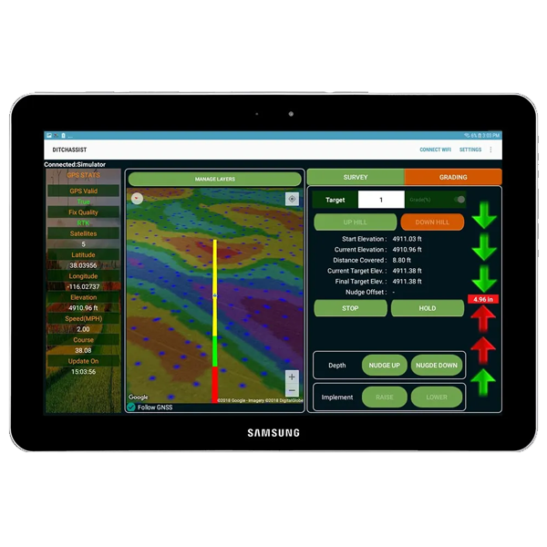
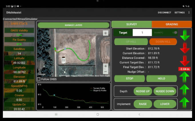
Grading Mode Screen Overview
The GRADING screen is split into three sections: the GPS (GNSS) STATS, the Map Window, and the Parameters & Controls Window:
GPS Stats (GNSS Info Window)
Information about your current GPS status are displayed here. Most are self-explanatory.
GPS Valid
The GPS Valid entry should be True, meaning that valid GPS messages are being received. A value of False here indicates that no GPS messages are being received
Fix Quality
It is important to wait until you achieve the required fix accuracy before you start working. Typically, you will want to see RTK here – whether you are running actual RTK or a subscription-based correction, the system will display RTK once convergence has been reached. Fix quality readings you may see:
Undefined: You have no GPS fix – you just powered on the system, or you are indoors!
GPS Fix: This is the most basic level of GPS signal quality. When a device has a GPS fix, it means it's receiving signals from at least four satellites and can calculate your geographic position. However, the accuracy is limited, typically within a range of 5-10 meters.
Differential GPS (DGPS): This is an enhancement to GPS which provides improved location accuracy, from the 5-10 meter nominal GPS accuracy to about 1-3 meters in case of the best implementations. DGPS uses a network of fixed, ground-based reference stations to broadcast the difference between the positions indicated by the GPS satellite system and known fixed positions. These stations broadcast the difference between the measured satellite pseudoranges and actual (internally computed) pseudoranges, and receiver stations may correct their pseudoranges by the same amount.
Float RTK (Real-Time Kinematic): Float RTK provides a medium level of accuracy, usually within a few centimeters. It works by looking at the number of full carrier phase cycles between a ground station and the GPS satellite, but the receiver isn't sure if it has the correct number of cycles. It's in a "float" state because it can't definitively resolve the number of wavelengths between the satellite and receiver.
RTK (Real-Time Kinematic GPS): RTK GPS provides the highest level of accuracy, typically within a few millimeters. Like Float RTK, it uses the carrier phase of the GPS signal, but the difference is that RTK has fully resolved or "fixed" the number of wavelengths between the GPS satellite and the receiver. This allows it to deliver a highly precise position. It's common to transition from a Float RTK to a RTK Fix as the system gains confidence in the number of wavelengths.
Map Window
The Ditch Assist App features a Google map window that can be used to display satellite imagery of your current location, load reference layers, and map/export the work you’ve done with Ditch Assist.
Storing Background Imagery for Offline Use with the Ditch Assist App
The Ditch Assist App's map feature enables you to simultaneously view Google imagery in the background and track your current location. As the map data requires an internet connection to download and the Ditch Assist Control Module's Wi-Fi doesn't provide internet access, it's necessary to preload or cache the map imagery before field use. There are two main methods to do this:
The first option is to access the app when connected to an internet-enabled Wi-Fi network. Manually navigate and zoom into your area of interest on the map. The background imagery will be cached (saved) onto your device as it loads, making it available for offline use in the field.
Alternatively, if you have a cell phone that allows tethering to your tablet, you can download the background imagery directly from the field. Simply connect to the Ditch Assist Wi-Fi and operate the app as usual. Next, on the map screen, click on the location icon located at the upper right corner of the screen. The map will automatically zoom in on your current location (though you'll only see a blank space if no imagery has been stored). After this, pull down from the top of your screen to access the settings menu. Open the Network settings and switch the Wi-Fi connection to your phone's hotspot. Use the back button to return to the Ditch Assist App, and you'll begin to see the background imagery appear. Once the imagery is downloaded, go back to the Network settings to reconnect to the Ditch Assist Control Module.
Please note, some devices may allow you to share an Internet connection between your cellphone and tablet via Bluetooth tethering, but this approach has not been validated by us.
Adding Background Reference Layers
Ditch Assist supports the use of both geo-referenced imagery using WGS84 geographic CRS as well as kml file overlays (the native format of Google Earth). Both formats can be exported from GIS applications such as QGIS.
KML Reference Layers
Reference layers such as flow routes and drainage designs may be imported and overlaid onto the map screen in kml format. The reference data should be in polyline format without excessively complex geometry. Very large files may cause the App or tablet to freeze.
To import kml layers, save the kml files directly onto the internal memory of your device. Using the Manage Layers button on the map window, you may then browse for and add/remove the layers using the workflow: MANAGE LAYERS > ADD > KML File
Image Reference Layers (jpg, png)
Ditch Assist supports georeferenced image overlays in PNG or JPG formats, with the JPG format usually offering the optimal balance between quality and file size. Importantly, the required coordinate reference system (CRS) for these formats is Geographic WGS84, not the typically used projected (UTM) CRS in GIS applications. Images must be exported from your GIS application using the EPSG: 4326 WGS84 geographic coordinates system and each image file should have an associated world file (.pgw, .jgw). Therefore, your exported image layer will consist of two files. For a .jpg, for example, you might have sample_image_overlay.jpg and sample_image_overlay.jgw - both files must be copied to the device and selected for import.
To import .jpg and .png image overlays:
First, generate the reference layers as outlined above and store them on the device's storage (like the Downloads folder). In the map window, navigate to Manage Layers > Add > Image File (png.jpg…) > find and select both the image and the world file by long pressing one file and then the other. Return to the Manage Layers screen, then use your tablet's Back button to exit the screen. If the process was successful, the image overlay will be added to the map, which will auto-zoom to the location after a few moments. To confirm the overlay is positioned correctly, zoom out on the map.
Image Reference Layers (GeoTIFF) in UTM Coordinates
Feature Coming Soon
Mapping Work Completed
While operating in Grading Mode, Ditch Assist will document the work performed locations as colored lines on the map screen. These lines will be color-coded to indicate whether the target depth has been reached. Green lines will be drawn on the map where the implement has successfully reached the target depth. Conversely, red lines will indicate areas where the target depth was not achieved. This feature is enabled by default but can be toggled on or off in the Settings.
When retracing the same route, for instance, making a second pass because the target depth was not attained on the first pass, new lines will be overlaid on top of the old ones. These will also be color-coded based on the achieved target depth.
This information can be utilized to identify areas requiring further work. Seeing green lines layered over red ones signifies the target depth has been reached, indicating you can proceed to the next section.
Exporting Mapped Data
Ditch Assist automatically logs both survey data and completed work data, storing it directly on your device. You can opt to save the data in a delimited text format (XYZ), or as a KML file through the Settings. For those using Ditch Assist to survey fields for exporting into drainage or land level design software, we suggest using the XYZ text format. This will produce a text file with three columns: X, Y (coordinates in decimal degrees) and Z (elevation in either feet or meters, depending on your chosen measurement system).
However, recent Android updates have modified the permissions regarding how we can write data (such as survey and ditching log files) to the device storage. This has caused some users to experience crashes when the app is unable to write data, even after obtaining the necessary permissions during the initial app setup. Starting from app version 4.20.5, we have shifted to saving data to the following directory:
Documents > Ditch Assist
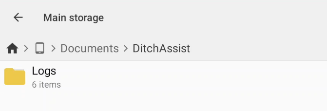
Survey files and as-built data are stored in the Documents > Ditch Assist > Logs folder on the tablet:
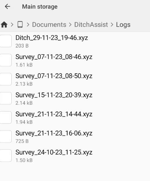
Typically, the built-in file manager on your device cannot access this location. To view the files here, we recommend installing a third-party file manager app like Cx File Explorer from the Play Store. Use it to navigate to the file location (keep in mind that you might need to give Cx permissions to access this location the first time you attempt to do so).
Grading Parameters and Controls
Start Elevation
Start Elevation on the Grading Screen refers to the elevation recorded when the 'Start' button is pressed. It's primarily used for tasks where you input a straight grade and then press Start. The target elevation at any given point is calculated based on the straight-line distance from your current location to this starting elevation. However, in grading models generated by Slope-IQ or in imported land leveling designs, this value typically doesn't carry any significance and can usually be disregarded.
Current Elevation
Current Elevation on the Grading Screen refers to the elevation at your current position. If you have entered any measurements or calibrations to the GPS height then the value shown here will be the adjusted value based on your inputted offsets
Distance Covered
Distance Covered on the Grading Screen is the straight-line distance from your current position to the start point. Not relevant for Slope-IQ or imported land leveling designs
Current Target Elevation
Current Target Elevation on the Grading Screen is the elevation that Ditch Assist aims to reach at your present location. The determination of this value will depend on one of the following scenarios:
i. In simple grading mode, the target elevation is calculated based on the straight-line distance between the Start Elevation and the Current Elevation. The target elevation is determined according to the grade entered by the user. For example, if you're 100 feet away from your start point where the elevation was 100ft, and you input a target grade of 1% working Downhill, the current target elevation would be 100 - (100*0.01) = 99ft.
ii. If a design was created using Slope-IQ and is currently being implemented, the target elevation will be the elevation value on the design that is nearest to your current location. If you're directly over the original survey route used to create the Slope-IQ design, the value will be derived from your location. If your current position is offset from the original survey route (for instance, to the left or right of it), then the target value will be taken from the nearest point on the original survey. This methodology allows you to create a wider drain or even grade an entire field based on a single central route survey.
iii. If a land leveling design, created in third-party software, has been loaded and selected for implementation, the Current Target Elevation will be based on the computed value from that design. You can find more detailed information on how Ditch Assist implements land leveling designs later in this manual.
This value is also influenced by the Nudge functionality. Nudging adjusts the Current Target Elevation by a certain increment set in the Settings. More details about what Nudging is and how it functions are provided below.
Final Target Elevation
Final Target Elevation on the Grading Screen is the same as the Current Target Elevation except it is not influenced by Nudge
Nudge Offset
Nudge Offset on the Grading Screen tells you how many inches you have ‘Nudged’ away from the Final Target Elevation – see explanation of Nudge feature below
Target Grade
The Target Grade field allows you to input the desired gradient for straightforward grading tasks. It isn't utilized for designs generated by Slope-IQ or imported land leveling designs. Ditch Assist calculates gradients in percentages, so the required grade should be entered as a %. Here are some examples of grades expressed in percent:
5% = 5' per 100' (or 50' per 1,000')
1% = 1' per 100' (or 10' per 1,000')
0.1% = 1' (12”) per 1,000'
0.05% = 0.5’ (6") per 1,000'
The Target Grade should be entered as a positive decimal number, like 0.1, irrespective of the direction of travel. The Uphill/Downhill toggle buttons are used to specify if you are working uphill or downhill (explained below).
Uphill/Downhill Toggles
The Uphill and Downhill toggle buttons on the Grading Screen enable you to determine the starting point (Point A) in relation to the outlet for simple manual grading. This feature is not used when employing Slope-IQ-generated designs or imported land leveling designs.
Choosing 'Uphill' tells the app that Point A is the outlet (lowest) point and Point B is uphill from Point A. Consequently, the necessary elevation will INCREASE as you move away from Point A.
Selecting 'Downhill' informs the app that Point A is the highest point and Point B is the outlet (located downhill from Point A). Therefore, the necessary elevation will DECREASE as you progress from Point A.
Start/Stop/Hold/Reset Button Functions

Tapping the START button on the Ditching screen enables automatic control (when the valve is installed), and kickstarts the visual up/down guidance. The Target Grade entered serves to calculate the necessary implement height in straightforward grading, whereas the Slope-IQ or imported land leveling design is used to determine the target elevation.
Once tapped, the Start button transforms into a STOP button. Pushing STOP immediately switches off automated control, and ceases all visual guidance and target elevation computations in the app. Pushing STOP won't remove any loaded parameters, thus allowing you to use START - STOP - START in succession to continue working on the same design or grading settings.
When START is active, the button to its right changes into the HOLD button. HOLD is designed to be used when manual control is necessary, but you still want to make use of the visual aids to observe the current target elevation - for instance, if you're operating manually and want to see how close you are to the finished grade so you know when you can switch on automation for the final pass. Tapping HOLD will pause the energizing of the PWM valve, but all other functions within the app will remain active.
The RESET button wipes all current parameters. Use this function to erase the current Point A and target grade parameters. After you hit reset, the next time you tap 'Start', a new Point A will be generated from your current location. Long pressing RESET will clear all map markers and loaded designs from Slope-IQ or imported land leveling designs.
Bear in mind that if you reset with a land leveling design loaded and wish to reload the same or a different design, you should close and reopen the app to ensure its correct operation.
Nudge Depth Function
The Nudge Depth function is designed to reduce the cut depth when the required depth is too significant to achieve in one go. This feature is applicable in any grading scenario, including implementing Slope-IQ and executing an imported land forming/leveling design. By tapping the Nudge Up or Nudge Down arrows, you can adjust the Current Target Elevation by the amount specified in the Nudge Sensitivity setting, which can be found in the Settings Menu.
The Nudge Depth feature does not modify the Final Target Elevation values. This means that you can continue working on subsequent passes without setting up a new start point in simple grading, and the original design remains unaltered in Slope-IQ or land forming. Here is a sample workflow when implementing a Slope-IQ design or imported land leveling design:
Pass 1: Suppose you foresee a cut depth that's too steep to accomplish in a single pass (for Slope-IQ grading, you can refer to the on-screen profile graph on the grading screen to view your current position relative to the design. When implementing a land leveling design, you can refer to the imported cut/fill map overlay). By tapping the Nudge Up button twice, you can temporarily raise the Current Target Elevation value by 4 inches (or by the value you've set each Nudge to represent). This raises the implement to cut 4" higher than the finished depth, allowing you to complete the pass without stalling. If Map Markers are enabled in Settings, the path will be marked red to indicate that you've worked on the route, but haven't achieved the final target depth.
Pass 2: When you return to the same spot a second time, press Nudge Down once to decrease the nudge offset to 2". The second pass will then cut 2 inches above the finished grade.
Pass 3 (or final pass): Upon reaching the final pass, press Nudge Down again to set the Nudge Offset value to zero. This allows you to reach the final target grade.
Implement RAISE and LOWER Buttons
Allows you to manually control the up and down movement of your implement from the tablet, and is useful for testing to confirm that Ditch Assist is working correctly. If you have installed the hydraulic bypass then you’ll most likely be using the tractor controls to manually raise/lower the implement, but you do also have the option to do it via the tablet.
Settings Menu Explained
Tapping on the ‘Settings’ tab will open the Settings Menu. Use your tablet’s back button to return to the main app screen at any time when in Settings
General
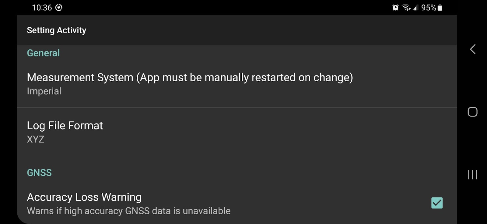
Measurement System
Allows you to switch between Imperial and Metric measurements for height and distance. The app must be force closed and reopened for the updated settings to take effect.
Log File Format
When you survey with Ditch Assist, as well as when you are grading, the log files are stored in your device memory at the following location:
Android>Data>com.AutoBotz.DitchAssist.MC
(note that you’ll need a third-party file manager app such as CX File Explorer to be able to access this location - see the section ‘Exporting Mapped Data’ earlier in the manual)
You can choose whether to record log files in XYZ text format, or in KML format. The default is XYZ, and this is the recommended format if you are using Ditch Assist to survey and then export the survey data for use in desktop software to design drainage or land leveling.
GNSS
Accuracy Loss Warning
If checked, an audible “beep” will be continually emitted from your device if RTK or subscription-based correction accuracy is lost. This is designed to alert you in the case that you lose GPS accuracy.
GNSS Message Delay Timeout

In case there's a temporary loss of GPS communication, Ditch Assist will keep operating based on the last received message. At times, GPS receivers may halt their transmission for a few seconds before resuming, and this typically doesn't cause any significant problems. However, if the GPS doesn't restart broadcasting position messages, we've incorporated this GNSS Message Delay Timeout feature. After this predetermined period, the app will automatically turn off automated control and notify the user about a GNSS issue. The default duration for this timeout is 30 seconds, but this can be adjusted as needed.
Transport Mode
Blade Height

The Blade Height parameter is used to correct the measured GPS height when performing a survey. It is assumed that the implement is fully raised up and in its transport position. The measurement entered here should be an accurate measure from the ground to the lowest point on the cutting edge while the implement is raised in transport position and parked on even ground. Enter the measurement in either inches or centimeters depending on the measurement system currently set.
Ditch Mode
GPS to Blade Height/Calibration Factor
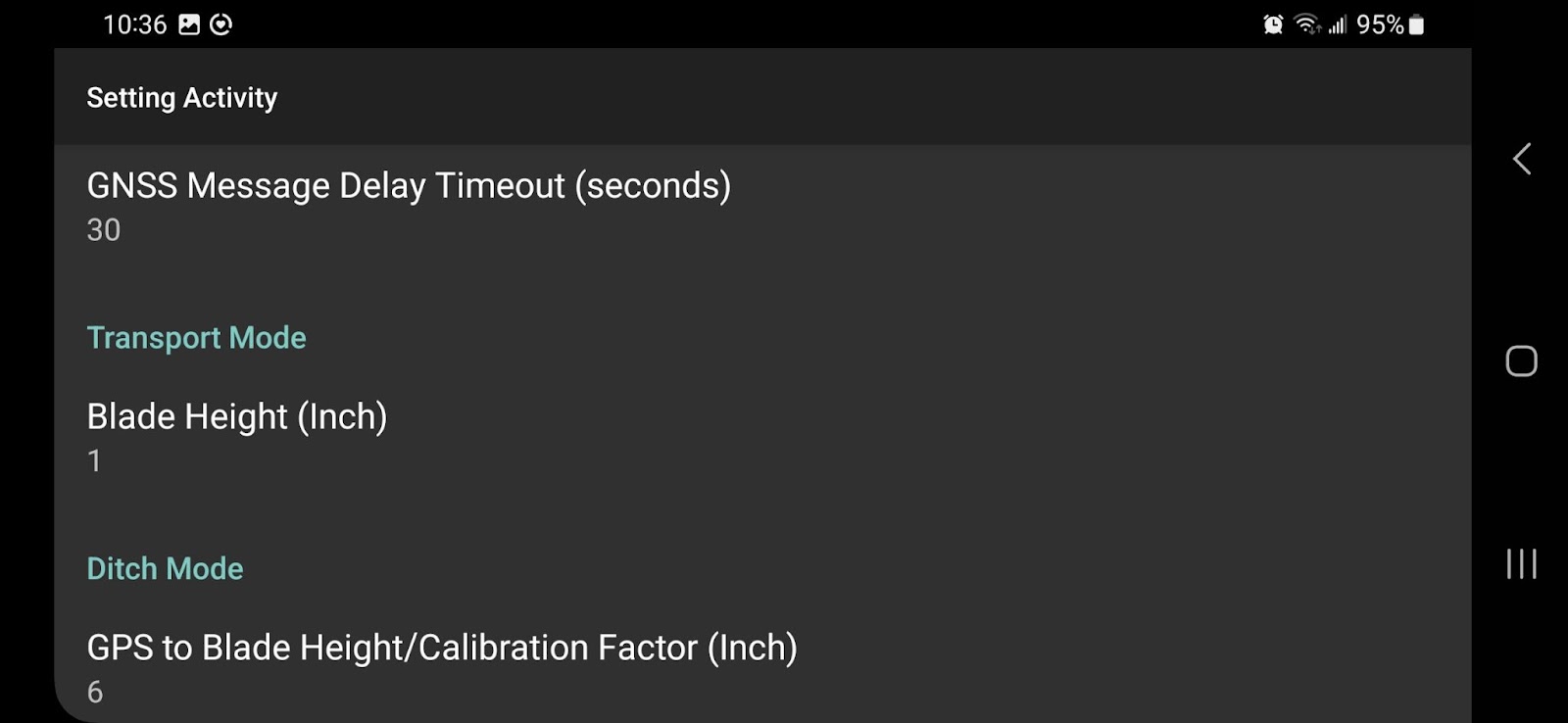
The "GPS to Blade Height / Calibration Factor" parameter is designed to offset the GPS antenna's height above the cutting edge and subtract this distance from the indicated GPS altitude to derive an accurate ground elevation. This is particularly useful in cases of surface and subsurface drainage, like when utilizing Slope-IQ. For this, the value should be the distance from the center of the GPS antenna (or another marker indicating the actual antenna's position within its casing) to the lowest point of the implement's cutting edge. If this measurement isn't provided or updated, it won't significantly affect your work as long as you don't adjust it mid-operation. However, the displayed GPS elevation may not be completely accurate.
This parameter can also be employed when executing a land leveling plan to align the current GPS elevation with the original survey. Especially when using mobile RTK base stations, and considering that agricultural GPS systems typically aren't calibrated in the same manner as survey equipment, there can be relative differences between the original survey heights and the current equipment. You can input a positive or negative value here to modify the reported GPS elevation until it aligns with a benchmark elevation from the initial survey. To streamline this process, we've introduced a feature called Auto Height Calibration, which is now the recommended method if this approach is necessary.
Inch/Arrow

The Inch/Arrow parameter specifies how many inches are represented by each arrow on the visual up/down guidance light bar located on the Grading screen at the far right of the screen.
Note that it is also possible to customize the distance represented by each arrow directly on the Grading screen by long pressing on an individual arrow and then adjusting the associated distance value. Any manual changes to individual arrows will override values set here.
Nudge Sensitivity

The Nudge Sensitivity parameter specifies how many inches the Current Target Elevation will be adjusted with each press of the Nudge Depth buttons on the Grading screen. Units will be either inches or centimeters depending on the Measurement System selected.
Response Sensitivity (Raising) & (Lowering)
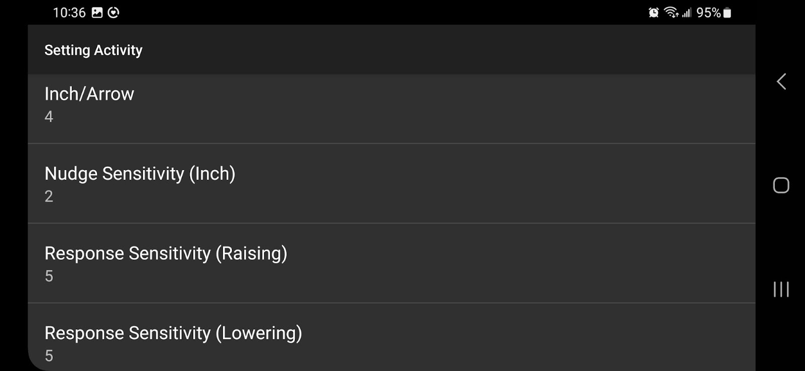
The Response Sensitivity settings for Raising and Lowering allow you to fine-tune the PWM valve's reactivity for manual control, that is, when you continuously press the manual raise/lower buttons on the Grading screen. The selectable value range is between 1 and 9, with the default being 5. This adjustment is only necessary if you find that your implement either responds too quickly or too slowly when you engage the manual raise/lower buttons. A lower value will slow down the valve's operation, whereas a higher value will speed it up. A setting of 9 will almost instantly deliver maximum flow at the valve, which could lead to unwanted movements and make it more challenging to lower to a specific depth. However, this setting doesn't impact the hydraulic response speed or movement during automated grade control - this is influenced by the Valve DC settings, which we'll discuss next.
Min Valve DC and Max Valve DC
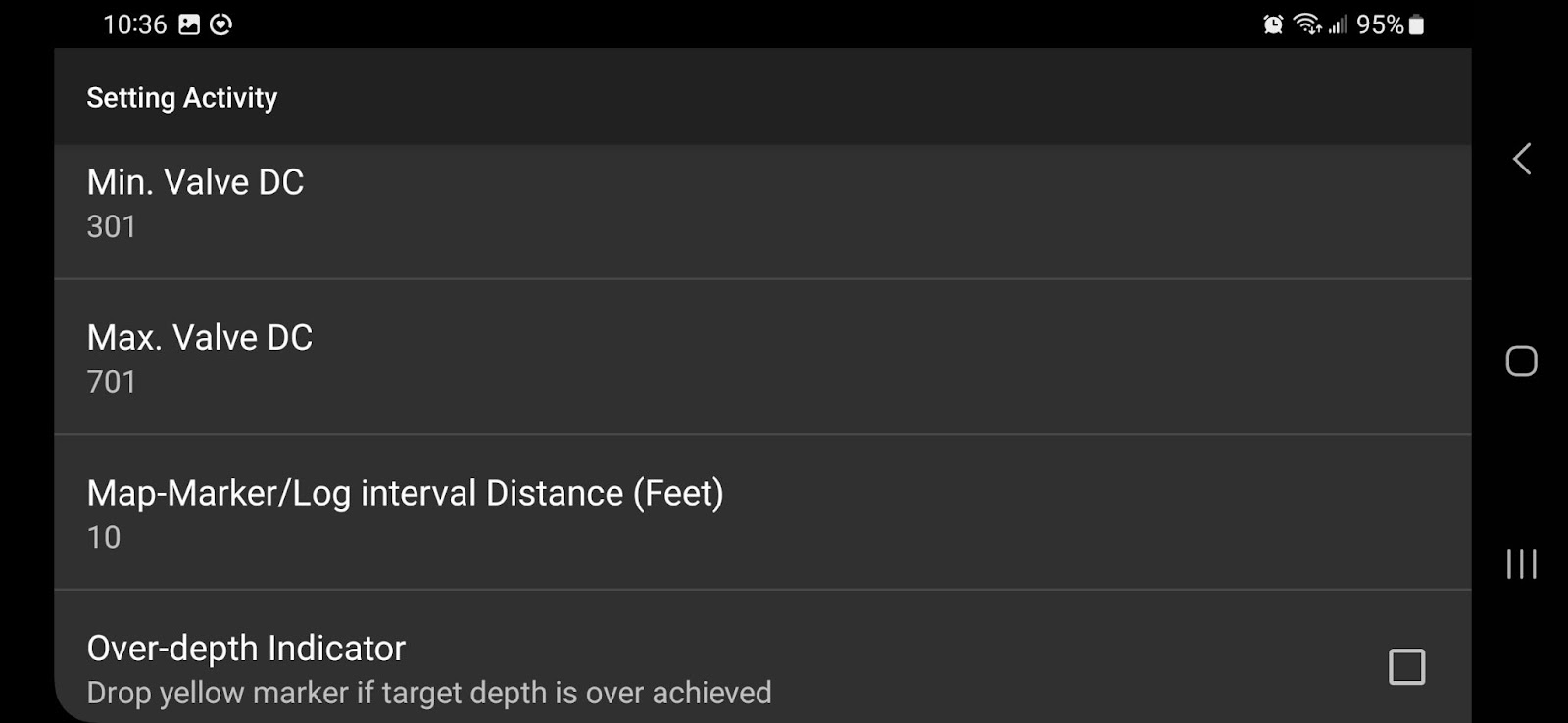
Min Valve DC and Max Valve DC are advanced settings that modify the duty cycle algorithm responsible for operating the PWM valve during automated grading mode. These settings should be carefully adjusted to fine-tune the hydraulic response, ensuring a suitable balance between rapid action and precise control. The goal is to drive the cutting edge to its target as quickly as possible without causing an overshoot that results in continual rapid adjustments as the system attempts to correct itself.
The Min Valve DC setting controls the initial speed at which the valve is energized and 'ramped-up' to implement the required elevation change within the first second of hydraulic movement—essentially determining the start of the response curve. Lower values equate to slower valve responses and a flatter curve, while higher values will lead to faster responses and a steeper curve. You can set this value anywhere between 0 and 1000. The default is 250, which should suit most applications. If your initial hydraulic response isn't quick enough (for example, on very rough ground), you may want to increase the value. This adjustment can also be beneficial for equipment with larger hydraulics. However, if your equipment has smaller hydraulics and the implement seems to exceed the target height, consider reducing this value.
The default Min Valve DC setting is 250.
The Max Valve DC setting modifies the valve's responsiveness when significant elevation changes are required, essentially determining the continuation of the response curve. For instance, it impacts the algorithm used when your implement suddenly begins to climb and the Control Module tries to lower the blade as quickly as possible. You can set this value between 0 and 1000, with the default set at 600, which should work well in most situations. If you're working on bumpy ground and finding that the machine doesn't respond quickly enough, consider gradually increasing the value to 700 or 800 for potential improvement. However, be aware that this could make the machine seem more 'jerky'.
The default Max Valve DC setting is 600.
CHANGING THIS SETTING CAN LEAD TO UNEXPECTED RESULTS, SO ALWAYS ADJUST IN SMALL INCREMENTS. START BY INCREASING THE VALUE FROM 250 TO 275, TEST THE SYSTEM, THEN CONTINUE TO INCREASE IN INCREMENTS OF 25 TO 50 TO FIND THE OPTIMUM SETTING. IT SHOULD NOT BE NECESSARY TO EXCEED 400/800 MIN/MAX IN MOST CASES, AS DOING SO MAY RESULT IN JERKY MOVEMENTS AND ‘OVERSHOOT’ CAUSED BY EXCESSIVE HYDRAULIC TRAVEL BEFORE THE NEXT GPS SIGNAL IS RECEIVED.
Your GPS accuracy also matters here. If you're not using RTK, increasing this setting may lead to lots of rapid up/down movements of the implement as it continually tries to compensate for GPS drift. If you're using less accurate GPS and observing unnecessary movements, try reducing the min and max values, say to 200 and 400, to see if it helps. You might experience slower responses, but it could lessen the impact of GPS inaccuracies.
Map Marker / Log Interval Distance

The Map Marker / Log Interval Distance parameter represents the distance that needs to be traveled before the painted coverage on-screen is updated. This parameter is also used to define the logging interval when surveying with Ditch Assist. The default is 10 feet, and usually it is not necessary to change this value.
Over-Depth Indicator

The Over-Depth Indicator setting provides an optional feature that allows you to mark areas on the map with yellow coverage indicators when you dig excessively deep or fail to reach the required fill depth in a certain area.
Grade Level Alert

The Grade Level Alert is designed for manual operation, and for Ditch Assist X operators, this will turn on an audible ‘beep’ whenever your blade or bucket edge is within the on-grade deadband.
Log Alert
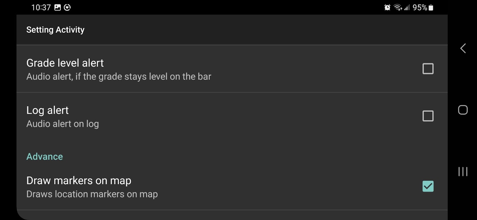
If the Log Alert setting is enabled, an audible ‘bing’ will sound each time a point is logged while performing a survey.
Advanced
Draw Markers on Map
Toggles ON/OFF whether grading coverage is painted to the map
Commands to Controller
Toggles ON/OFF whether the Control Module will energize the PWM valve. In the event you do not require automated control for an extended period (e.g. when operating manually) you may use this setting to turn off automation while still using the app in the normal way.
Autobotz Controller
Currently all functionality under this menu heading is for beta testing purposes only, and can be ignored. Please make sure that the checkbox Use ABZ Controller remains unchecked
UI
You have the option to enable or disable the GNSS Panel, Map Panel, and Mode (Parameter) Panels on the Grading screen as per your requirements. For instance, if you don't use the map, you might choose to hide it to allocate more screen space to other panels. Similarly, some users prefer to turn off the GNSS info panel to increase the size of the map for better visibility.
Ditch Assist Workflows Explained
Simple Grading (Surface & Subsurface Drains)
As discussed earlier, one of the simplest applications for Ditch Assist is to use it like a laser level to create consistent straight grades—for instance, creating a surface drain with a consistent 0.1% gradient. A common workflow might look like this:
- If necessary, conduct a survey of the proposed route to calculate the average grade between point A and B.
- Navigate to the Grading screen and input the desired gradient into the Target Grade box.
- Specify the direction of grading—choose uphill if you're starting at the outlet and working toward the inlet, and vice versa.
- Lower the implement to the desired starting position—this should be on the ground at the location where you intend to initiate grading.
- Press START and begin grading away from the starting point.
- As you progress, the system calculates the target elevation based on the distance covered and the gradient you input, using a straight-line distance.
- Utilize the STOP, HOLD, and NUDGE functions as necessary to empty the pan and tweak the cut depth until the desired final grade is attained.
- If you need to implement grade breaks along the route, press RESET to erase all previous parameters, input a new grade, and start the process again.
Leveling a Pad or Large Area
Creating a level area is simple with Ditch Assist. Using the method outlined above, you can set the finished grade level by either:
- Entering a grade of zero and starting from a location that is already at the required final grade level, or
- Using the method above, and then nudging down to set the final grade level to be a set amount deeper than the start location
- Entering an elevation value in the Target Grade box by toggling the box to accept an elevation value instead of a grade. In this case, Ditch Assist will use the target elevation you have entered as the Final Target elevation.
- Note: If the elevation value you're using is based on an accurate survey, it's recommended that you carry out a calibration using a known benchmark. Adjust the displayed GPS elevation to match the benchmark elevation by modifying the GPS to Blade Height/Calibration Factor parameter in the Settings. This adjustment ensures your final grade aligns accurately with the original survey.
Using Slope-IQ for Best-Fit and Customized Drain Design
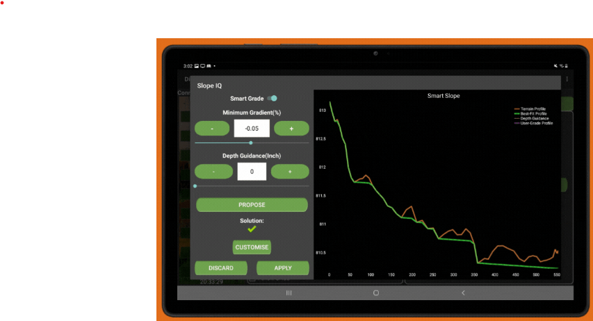
Slope-IQ is a feature designed to create optimal drainage paths, suitable for both surface drains (such as ditches) and subsurface drains (like tile runs). Using the data gathered from a survey (as mentioned earlier), it computes a best-fit solution according to the user-defined minimum slope parameters. Whenever the current landscape poses an obstacle to water flow at the specified minimum slope, Slope-IQ ensures the slope remains at the minimum grade. In essence, it 'cuts' through the obstruction, facilitating a consistent water flow.
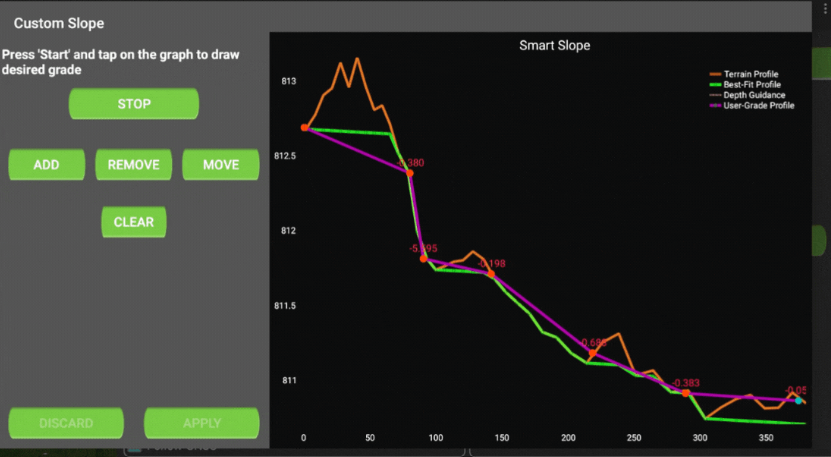
Slope-IQ also includes a customizer tool, giving users the power to design their own solutions. When using this feature, any previously specified minimum slope parameters are disregarded. The user can then 'sketch' their desired actions directly on the profile. This feature has been highly appreciated by existing users as it allows them to include fill areas (e.g., filling a low area instead of carving a ditch from its bottom), and adjust final outlet elevations. This is particularly useful for tile drainage installations, offering superior control over tile depths and slope breaks compared to many other systems.
Using Slope-IQ for Best Fit Drains
Slope-IQ requires the intended route to be surveyed using the Survey mode. Once the survey is finished (after hitting 'Stop'), the Slope-IQ button on the survey screen will become enabled.
You also have the option to import a previously conducted survey and load it into Slope-IQ. To do this, click on 'Manage Layers' on the 'Map' tab, navigate to 'Device' > 'Documents' > 'Ditch Assist' > 'Logs' and find the survey you need based on the date and time. Once it's loaded, the Slope-IQ button will be activated, as described before.
How To use Slope-IQ:
- Complete a survey or reload a prior survey using the steps outlined above.
- Press the 'Slope-IQ' button on the 'Survey' screen.
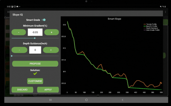
- Enter a minimum gradient value – this represents the lowest acceptable slope at any point along the run for the new drain, expressed in percentage (%). Generally, values above 0.05% (ideally 0.1%) are considered suitable minimum slopes for surface drains, but the ultimate decision rests with you!
- The tool assumes the lowest end of the survey is the outlet, defaulting to a positive grade representing a downhill slope from the highest to the lowest points. This assumption is usually correct, but not always. For instance, if you're draining a low point in the field that is lower than the outlet point where the drain will exit the field, you should adjust the minimum grade to a negative value (e.g., -0.05 instead of 0.05). This tells the calculator that you want the higher end of the survey to serve as the outlet point.
- Optionally, you can input a value for 'Depth Guidance.'
- This won't affect the calculated solution but will display an additional line on the profile representing the specified depth. This can be useful for visualizing the potential depth of your cuts – when the proposed solution crosses the depth guide line, the required cut will be that depth.
- For tile drainage installations where you require a minimum and/or maximum depth, this function can be used to confirm the solution is feasible. For example, if your maximum required depth is 6ft and the minimum is 2ft, set a depth guide line at 4ft. If the solution profile crosses below the 4ft line, it means you won't be able to maintain a minimum depth of 2ft AND a maximum depth of 6ft at that location.
- After inputting your parameters, click 'Propose.'
- The proposed solution is then shown on a profile (green line) along with the existing topography along the route (orange line), and a grade guidance line (if entered).
- Where there's enough natural slope, the solution line will follow the land's natural contours.
- If the natural contours impede maintaining the minimum slope, the solution will display a 'cut' through the region, maintaining the minimum slope.
- When implementing the drain, you may opt to slightly lower your target elevation to cut a small channel where the solution runs along the natural contours. In this case, remember that your deeper cuts may also need to be proportionately deeper to maintain the minimum slopes.
- If you are satisfied with the proposed solution, press APPLY
- Alternatively, adjust your minimum gradient value and click Propose again or create a customized solution (see below).
Once you have created a design using Slope-IQ and clicked APPLY you'll be returned to the Survey Screen. To load the design into the Grading Screen click IMPLEMENT SLOPE-IQ.
Creating a Customized Design Solution using Slope-IQ
Upon reaching Step #7 in the process described above, you can choose to customize the design and create your own. We recommend taking some time to familiarize yourself with the design tool before heading out to the field. This will ensure you understand its operation and functions.
Please note: When opting for a custom design, the original solution is disregarded, and only the design you sketch will be implemented. If you have a long drain and only wish to customize a small section of it, you might prefer to design only that part, then survey the rest and use Slope-IQ to generate a best-fit solution. Alternatively, you can design the entire length – the decision is yours! Just remember, if you don't draw your design from start to finish, there will be gaps in your design where the target elevation will not change. In these cases, Ditch Assist will continue using the last known value from your design as you move away from that location and your drain may have no grade.
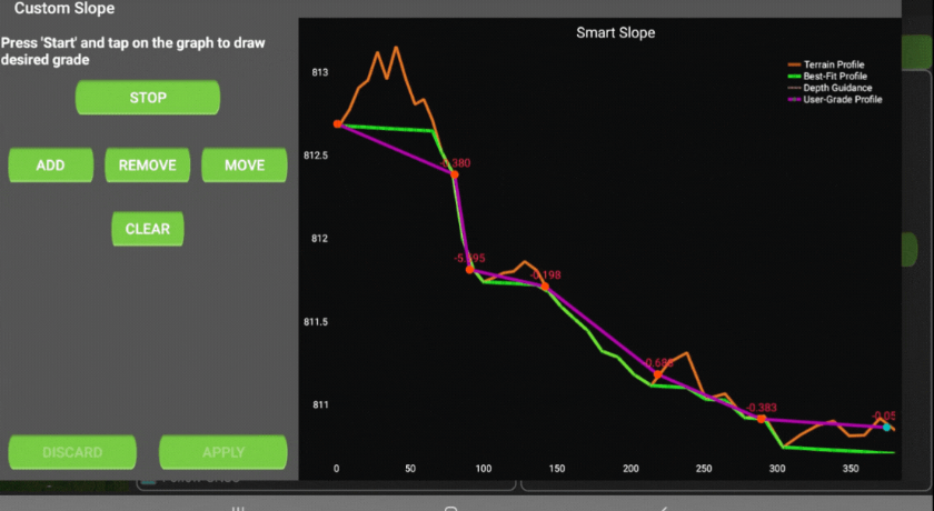
In this example, we have chosen to remove a little more of the hill near the inlet point, and will then use this material to fill areas downstream somewhat so that our outlet doesn’t need to be deeper than the existing ditch it will drain into.
For greater precision in your designs, we recommend using a stylus when creating custom designs.
Follow these steps to create your design once you have created an initial best-fit design (steps 1-6 above):
- Click on the 'CUSTOMIZE' button.
- Click 'START'.
- Click 'ADD', then tap a point on the profile that represents either the inlet or the outlet of the drain. A point will appear at the location.
- Click 'ADD' again and repeat the process to add another point. A straight line will be drawn between the two points, representing a proposed cut line.
- The gradient of the line in % will be displayed to provide you with the gradient information.
- To remove a point, tap it to highlight it and press 'REMOVE'.
- To move a point, tap on it, press 'MOVE', then tap on the new location on the profile where you'd like to move it.
- To clear the entire design and start over, press 'CLEAR'.
- Once you are satisfied with your design, click 'STOP' then click 'APPLY'.
Once you have created a design using Slope-IQ and clicked APPLY you'll be returned to the Survey Screen. To load the design into the Grading Screen click IMPLEMENT SLOPE-IQ. You’ll then be taken to the Grading Screen, and when you click Start your design will form the basis for the target elevations.
Using Ditch Assist to Implement Land Leveling / Land Forming Designs from Desktop Software
XYZ Design File Specifications
Ditch Assist is a very capable grade control system for implementing land leveling designs from several popular desktop software applications. A 3D landforming design must be exported in a tab delimited text (.txt) file format and contain the following three columns with no headers:
- Column 1: Latitude in Decimal Degrees
- Column 2: Longitude in Decimal Degrees
- Colum 3: Target Elevation in Metres
- Note that the target elevation MUST be in metres regardless of whether the Measurement Units in the Ditch Assist settings are set to metric or Imperial
When viewed in Notepad or a similar program, the design file will look like this example representing a field in Costa Rica (obviously your coordinates and elevation values will differ):
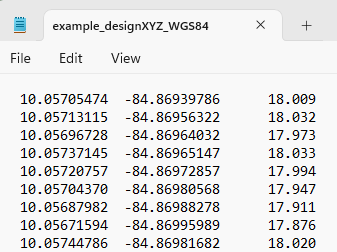
Cut/Fill Map Overlay
A cut/fill map may also be imported into Ditch Assist and used for visual reference. See the chapter on Adding Image Reference Layers for more information
Importing and Implementing a Land Leveling / Landforming Design
- Save the .txt design file to your tablet - the simplest way is to email it to yourself, open the email on the tablet, then save the design into your Downloads folder
- From the Grading screen, click on Manage Layers above the map
- Click ADD and choose the option XYZ Design File
- Navigate to the location you saved the design file and select it
- You’ll be returned to the Manage Layers window. Tap the Back Button on your tablet once
- If the file is recognised as a correctly formatted land level design file, a prompt will appear asking you if you’d like to implement the design. Click YES
- You’ll be taken back to the Grading Screen, and the map will zoom to the design location. Verify the location is correct
- If required, perform a GPS calibration to ensure the current GPS elevation is calibrated with the original field survey (see below for instructions)
- Pressing START on the Grading screen to begin working. Ditch Assist will compute the target elevation value from the design file and constantly adjust the implement hydraulics to meet the target
- Utilize the STOP, HOLD, and NUDGE functions as necessary to empty the pan and tweak the cut depth until the desired final grade is attained.
Calibrating the GPS Elevation using Auto Height Calibration
Auto Height Calibration makes calibration of the current GPS elevation to the original survey elevation simple. There are two methods that can be used:
- Loading a XYZ design then driving to a location that will remain unchanged (i.e. have no cut or fill) and calibrating based on the design elevation at that location, or
- Using a benchmark with a known elevation that was established during the initial field survey, lowering the implement to the benchmark elevation, and then entering the known elevation into the tool
Using the XYZ Design File for Calibration
- Import the XYZ design file into the Ditch Assist App.
- Navigate to a spot included in the design that won't undergo changes and let the implement rest on the ground. Utilizing a cut/fill map might be useful in identifying an appropriate location.
- Tap on the three vertical dots at the top right corner of the screen and select 'Auto Height Calibration'.
- An Auto Height Calibration window will appear, displaying the current design elevation and the present GPS elevation. If these values differ, a calibration factor will also be shown. This value indicates the adjustment that will be automatically applied to the GPS to Blade Height / Calibration Factor parameter in Settings.
- Tap 'Set'.
- Confirm correct calibration by pressing START on the Grading Screen. If the calibration is accurate, the off-grade distance displayed on the visual guide deadband should be close to zero, with minor fluctuations due to GPS drift.
Using a Known Benchmark Elevation for Calibration
Using the same process outlined above, this time park with the implement blade at the same elevation as the known benchmark. In the Auto Height Calibration window, toggle the selector to Manual, and enter the known elevation in the same units as shown next to the Current Elevation value (feet or metres). Tap SET and then verify the displayed elevation on the Grading Screen matches the benchmark elevation.
Common Troubleshooting Steps
Cannot Connect to Ditch Assist Wi-Fi
You connected the tablet to the Ditch Assist WiFi network, but in the Ditch Assist App you cannot connect to the Control Module (nothing happens when clicking ‘CONNECT WIFI’).
When initially setting up the WiFi connection on the tablet you may need to acknowledge the connection has no internet but you’d still like to connect to it.
If you see a notification like this, click on ‘Always Connect’ or similar so the tablet knows you always want to connect to Ditch Assist even though it has no Internet connection
Verify the tablet has not disconnected from the Ditch Assist WiFi and connected to another known WiFi connection that has Internet available
Go to WiFi Settings and ‘forget’ all WiFi networks that are not Ditch Assist if this is happening
Confirm Control Module is powered on.
Confirm that the Operating Status LED is illuminated
Ensure there are no obstructions, particularly solid metal objects, between the Control Module and Android device, or that the distance isn’t too great.
Try bringing the tablet close to the Control Module to eliminate this variable - if still no connection, move on.
Confirm that no other device (e.g. your cell phone) is currently connected to the Ditch Assist Module.
Only one connection is allowed at one time - if you’ve previously used your cell phone to connect to Ditch Assist go into the phone settings and ‘forget’ the connection.
Power cycle the Control Module and force close the Ditch Assist App, then attempt connection again
Wi-Fi Connection keeps dropping
You seem to be losing WiFi connection to the Control Module when working. Automated control keeps cutting out. GNSS information stops updating.
Usually caused by same factors listed above
Has been reported when using Android devices with inferior WiFi components and slow memory
Try a recommended tablet
Try to bring Control Module closer to the tablet
Pressing RAISE on Manual Control causes implement to go down
When you press the RAISE button on the grading screen to manually raise the implement it goes down instead. Pressing LOWER also has the opposite effect.
Reverse the connectors on the Ditch Assist harness that are connected to the PWM valve
Switch the Raise and Lower connectors to the opposite solenoids
DO NOT REVERSE HYDRAULIC FLOW ON THE TRACTOR. THIS ACTION IS INEFFECTIVE AND CAN CAUSE INCREASED PRESSURE IN THE RETURN LINE AGAINST THE VALVE, OBSTRUCTING FLOW WHEN YOU SWITCH BACK TO THE PROPER FLOW DIRECTION.
Difficulty Releasing Hoses from Quick-Release Hydraulic Fittings on the Valve
This issue often arises when the hydraulic flow from the tractor is inadvertently reversed, leading to pressurization in the return line. It's more frequent during hot weather conditions, but can occur unexpectedly at any time.
Ensure the hydraulic flow to the valve is turned off.
Use the Ditch Assist App and firmly press and hold the 'UP' manual control, followed by the 'DOWN' control, each for approximately 5 seconds. This action is aimed at balancing the pressure between the tractor and the implement.
Make sure the Control Module is powered on and the tablet is connected to it before performing this step
If the hoses remain attached, repeat the process until you can successfully release them.
Implement goes back Down after I Manually Raise it
Usually this is because you still have Auto Grading enabled, so the control system is trying to return the blade to the target elevation.
Make sure you press the STOP button to disable automated control before manually raising
No Hydraulic Control of Implement
The hydraulics don’t move at all either when using manual RAISE or LOWER, or in Auto Grading mode.
Confirm valve is correctly connected to both implement raise/lower and tractor hydraulics.
Consult the valve setup diagram for your PWM valve and confirm correct setup.
Verify no couplers popped out of tractor SCVs or valve couplers.
Confirm you have constant flow turned on for the circuit the valve is connected to.
Verify solenoids on PWM valve are being energized when pressing manual RAISE or LOWER on the Ditch Assist App.
Usually you can hear or feel the vibration when they are
Hold a metal object to the solenoids - they will magnetize when energized
Check Min and Max DC Settings in Ditch Assist App Settings.If they are set too low the blade will not move
Increase the Min Max DC values for auto grading responsiveness.
Increase the setting for Manual Raise Lower Sensitivity for manual responsiveness.
Ensure tractor hydraulic flow is turned up enough to move the implement hydraulics.
Turn UP tractor flow.
Verify hydraulic fittings are not leaking and causing a drop in pressure
Are you using a Closed Center valve on an Open Center tractor?
If so, contact your dealer for solutions
Implement Hydraulics seem Slow to Respond/Implement will lower but not raise
Often characterized by the implement slowly lowering, but unable to raise against its own weight, particularly with larger scrapers.
Turn up the hydraulic flow on the tractor to the valve
Be sure you have your hydraulics in constant flow (not in float)
Are you using our Closed Center valve on an open center tractor?
Increase the MIN and MAX valve DC settings in the App
If these are set too low the valve will never allow enough flow to move a larger implement
Try values around MIN: 400-500 and MAX: 750-800, if nothing happens here then there’s likely another issue
No GPS Connection, GPS Not Working, No GPS/GNSS Info Shows in Ditch Assist App
When you hit CONNECT WIFI you should immediately see GPS/GNSS info populate in the GNSS Stats tab down the left of the screen. If you don’t it could be for one of these reasons:
WiFi not connected to Ditch Assist Control Module
Confirm the tablet is connected to Ditch Assist and not another WiFi network
GPS not connected or configured
Verify GPS receiver is connected to the Ditch Assist harness and powered on
Confirm required NMEA messages (GGA and VTG) have been enabled, and baud rate is set to 38,400
Turn OFF any additional messages as these can cause conflicts
Verify GPS messages are being received by the Control Module
For CAN GPS messages (e.g. Outback smart antennas), the STATUS 1 LED on the module should blink if messages are being received
For RS232 NMEA messages (most receivers) the STATUS 2 LED should blink
If neither STATUS 1 or 2 is blinking then the Control Module is not receiving valid GPS messages
Confirm correct GPS cable and pinouts for Tx and Rx
If using DB9 serial cable, try switching pins 2 and 3 (Tx and Rx) on the GPS connector on the main Ditch Assist harness
Disconnect the Tx pin (pin 3) on the GPS connector on the Ditch Assist main harness (sometimes having this connected causes signal loops with some receivers, and it is not required as Ditch Assist only needs the Rx and signal ground)
Confirm all pins are correctly seated on GPS connectors and Ditch Assist harness
Keep Losing RTK Fix - Displayed GPS Fix Quality Bounces from RTK to GPS Fix
Your GNSS Fix Quality status keeps going from RTK to FLOAT or GPS Fix. When this happens you lose all grading accuracy and the implement either raises out of the ground or tries to bury itself deep into the ground.
This is usually a GPS issue, not an issue with Ditch Assist as the fix status is determined by the GPS:
Make sure your GPS is mounted with a clear sky view and no obstructions to the horizon in all directions
Ensure you aren’t too far from your base station if using one.
If using cellular RTK you may be dropping connection or the network may have high latency
If you lose RTK fix when going over very bumpy ground you may have a loose radio or GPS receiver board inside your GPS antenna, or a faulty cable, or you may need to re-design your GPS mount to reduce vibration.
Check power to the GPS receiver
Make sure fuses are pushed in on Ditch Assist power harness
Verify power is coming from tractor battery, and power harness is not connected to an auxiliary plug, trailer plug, or power strip
Confirm all connectors are properly seated
I’m using John Deere SF3 or StarFire RTK and Ditch Assist doesn’t show I have RTK even when I know I do. It shows DGPS instead.
When using John Deere SF3 or StarFire RTK with Ditch Assist, the app might not display the RTK status even if you are certain it's active. This discrepancy is due to how the GGA message's fix status part is interpreted.
In the GGA message, a numeric value indicates the fix status. For an RTK fix, this number should ideally be '4'. However, John Deere receivers using SF3 or StarFire RTK emit a value of '2' in this field. In industry-standard terms, a '2' is decoded as 'Differential Correction', akin to a WAAS/SBAS type correction, not RTK. Therefore, when Ditch Assist decodes this message, it follows these standards and interprets the '2' accordingly. As a result, the Ditch Assist App displays the status as Differential Correction (WAAS/SBAS) instead of RTK.